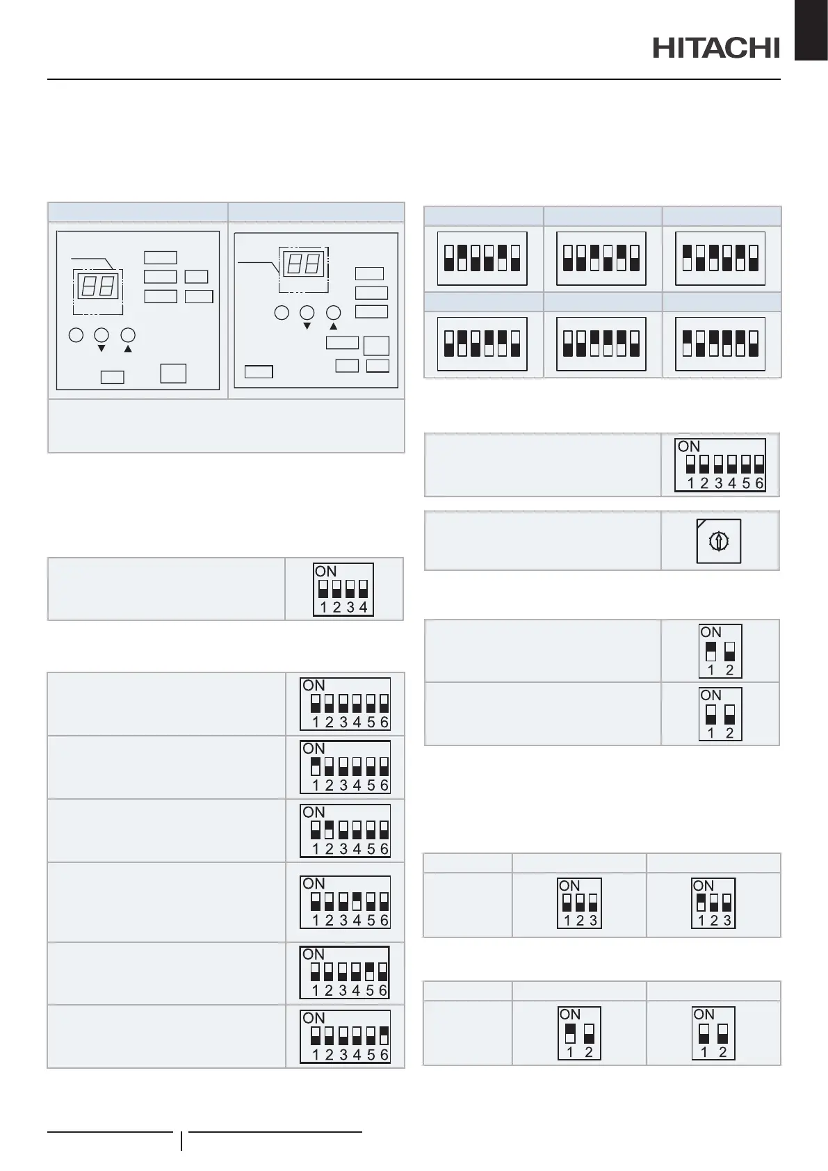
10.2.1 Setting of DIP switches for outdoor unit
Quantity and position of DIP switches
The location is as follows:
RAS-(4-6)HV(R/N)(C/P)2E (PCB2) RAS-(4-6)H(R/N)(C/P)2E (PCB1)
SEG1
DSW4
DSW2
DSW7
DSW3
DSW6
RSW1
PSW1 PSW2 PSW3
DSW1
Display
(7SEG)
DSW5
DSW1
SEG1
DSW4
DSW2
DSW7
DSW3
RSW1
PSW1 PSW2 PSW3
DSW6
Display
(7SEG)
DSW1 and PSW can be operated while power source is ON.
It may take up to 20 seconds for the change of operation state
! CAUTION
BeforechangingthesettingsoftheDSWs,thevoltagesupplyshouldbe
disconnected.Otherwise,thenewsettingswillnotbevalid.
DSW1: For test run
Factory setting
DSW2: Optional function setting
Factory setting
Control to support existing pipes or when using
Ø19,05 gas pipe (soft-annealed), switch ON
DSW2 pin 4 in the outdoor unit PCB
Optional function setting mode
(The optional function selection mode
becomes available)
becomes avaliable).
DSW3: Capacity
Factory setting
RAS-4HV(R/N)(C/P)2E RAS-5HV(R/N)(C/P)2E RAS-6HV(R/N)(C/P)2E
RAS-4H(R/H)(C/P)2E RAS-5H(R/N)(C/P)2E RAS-6H(R/N)(C/P)2E
DSW4 / RSW1: Refrigerant cycle number setting
Factory setting
(Setting for the tens digit)
Factory setting
(Setting for the last digit)
0
9
8
7
6
5
4
3
2
1
DSW5: Transmission setting of end terminal
resistance
Factory setting
Cancellation
In the case that the outdoor units quantity in the same H-LINK
is 2 or more, set No. 1 pin of DSW5 at “OFF” side from the 2nd
refrigerant group outdoor unit. If only one outdoor unit is used,
no setting is required.
DSW6: Not used
Factory setting
(Do not change)
DSW7: Not used
Factory setting
(Do not change)
Electric wiring
PMML0545 rev.2 - 04/2021
15
EN

 Loading...