2 3
3
4
5
0.5
1 3
6 10 20 30 40 50 60Hz
-100
-200
200
100
0
Speed (min
-1
)
(%)
Torque
Deceleration Time:
4.2 sec.
Deceleration Time:
1.9 sec.
OFF ON
Motor Current
DC Voltage
Output Frequency
DC Vol tage
Output Frequency
Motor Current
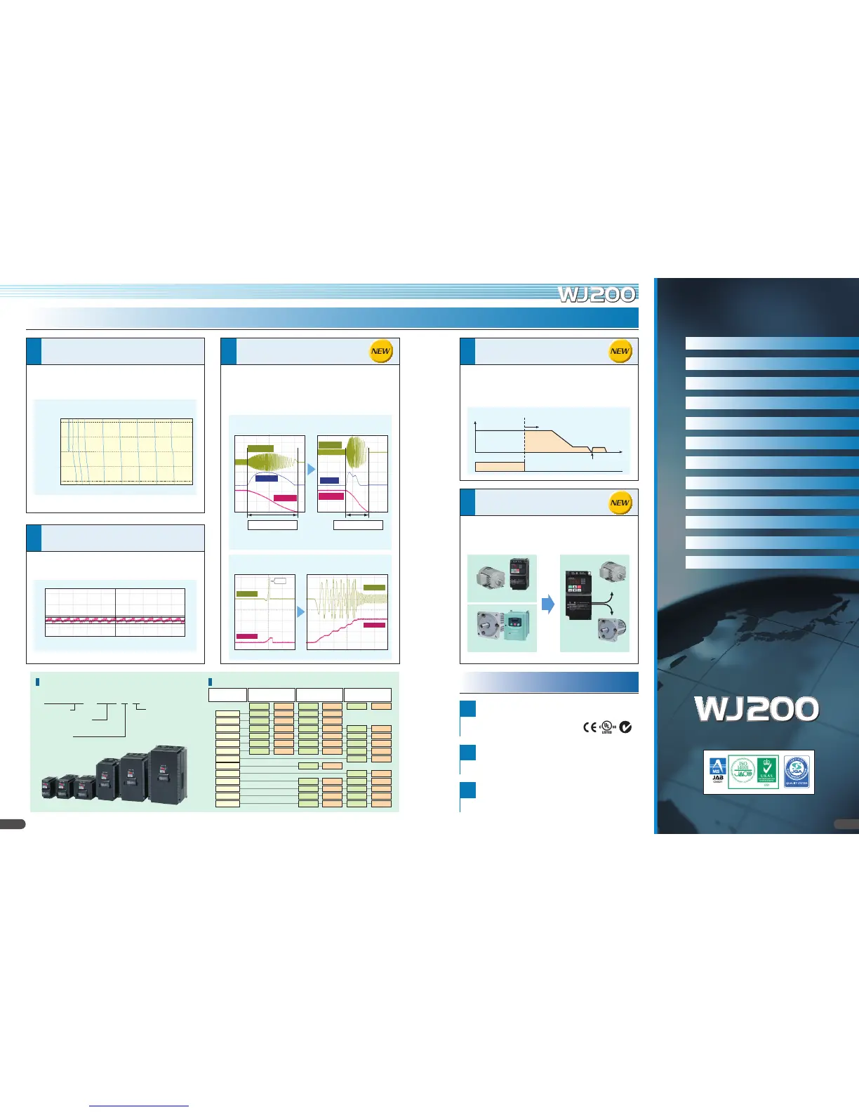
Pursuing the Ideal Compact Inverter
Designed for excellent performance and user friendliness
Industry-leading Levels of Performance
High starting torque of 200% or greater achieved
by sensorless vector control
(
when sized for heavy duty
).
Speed regulation at low-speed is greatly improved.
–
Fluctuation is 1/2* compared with the previous model.
–
Trip avoidance functions
Conformity to global standards
Sink / source logic is standard
Wide input power voltage range
Simple positioning control
(when feedback signal is used.)
Induction motor & Permanent magnetic motor*
control with one inverter
(corresponds more than Ver.2.0)
1
2
1
2
3
Integrated auto-tuning function for easy sensorless vector control
realizes high torque suitable for applications requiring it such as crane
hoists, lifts, elevators, etc.
Minimum time deceleration function, over-current suppress function
and DC bus AVR function are incorporated. The functions reduce
nuisance tripping. Improved torque limiting/current limiting function
enables a load limit to protect machine and equipment.
Speed regulation at low speed has been drastically improved to
enhance process stability and precision.
CE, UL, c-UL, c-Tick approvals.
Logic input and output terminal can be congured for sink or source logic.
Input voltage 240V for 200V class and 480V for 400V class as standard.
When simple positioning function is activated, speed control operation or
positioning control operation is selectable via intellient input. While the [SPD]
input is ON, the current position counter is held at 0. When [SPD] is OFF, the
inverter enters positioning control operation and the position counter is active.
The WJ200 inverter can drive both induction motors (IM) and permanent
magnetic motors (PM). Energy conservation and miniaturization can be
achieved using PM motors. Moreover, one inverter used for two types of motor.
Output Frequency
Start position counting
Speed control Position control
Target position
DB
Time
SPD input
ON
Example of Torque Characteristics
Model ConfigurationModel Name Indication
WJ200 – 001 L F
with Digital Operator
Power Source
S: 1-phase 200V class
L: 3-phase 20 0V class
H: 3-phase 4 00 V class
Applied Motor Capacity
001: 0.1kW – 150: 15k W
Series Name
PM
WJ200
IM
IM + Inverter
PM + Dedicated Controller
Auto-tuning to perform sensorless vector control can now be easily done.
Model Name
WJ200-xxx
1-phase 200V class 3-phase 200V class 3-phase 400V class
VT CT VT CT VT CT
001 0.2 0.1 0.2 0 .1
002 0.4 0.2 0.4 0.2
004 0.55 0.4 0.75 0.4 0.75 0.4
007 1.1 0.75 1.1 0.75 1.5 0.75
015 2.2 1.5 2.2 1. 5 2.2 1. 5
022 3.0 2.2 3.0 2.2 3.0 2.2
030 4.0 3.0
037 5.5 3.7
040 5.5 4.0
055 7. 5 5.5 7. 5 5.5
075 11 7. 5 11 7. 5
110 15 11 15 11
150 18.5 15 18.5 15
(Example of WJ20 0-055LF)
• Frequency commanded by the inverter: 0.5Hz.
• Motor: Hitachi's standard 3-phase 5.5kW 4-pole totally enclosed type motor.
Example of Hi tachi's standard motor. (7.5kW 4-pole)
2.3 sec. reduction of deceleration time without a braking
resistor is achieved when the function is active.
Over-current Suppress Function*
Minimum time deceleration Function
(Example of WJ200-075L F)
* WJ200: 5min
-1
, Previous model: 13min
-1
*Turn of f this function for lifting equipment.
*Per manent magnet motor control function of WJ200 is for variable torque application such as fan and pump.
EC97J1095
Features P2–5
Standard Specications P6
General Specications P7
Dimensions P8
Operation and Programming P9
Terminal (Arrangements/Functions) P 10 – 11
Function List P 12 – 20
Protective Functions P 21
Connecting Diagram P 22– 23
OFF ON
Motor Current
Output Frequency
Motor Current
Output Frequency
Trip
Connecting to PLC P 24
Wiring and Accessories P 25
For Correct Operation P 26 – 27
Global standards
Index
3

 Loading...


