Do you have a question about the Hitachi WJ Series and is the answer not in the manual?
Defines warning indications and symbols used for safety precautions.
Provides important precautions for proper use, installation, wiring, operation, maintenance, and disposal.
Details EMC and Machinery Directive compliance requirements and notes for European markets.
Summarizes requirements for UL standard compliant inverter installation, including fuse ratings and wiring.
Explains the scope, target audience, unit system, and what this guide covers.
Provides a step-by-step flowchart for installing a new inverter and replacing WJ200.
Details what to check upon unpacking and confirming the product and included items.
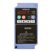
Shows the appearance of different inverter models and identifies their parts.
Outlines precautions for installation, including transportation, ambient temperature, humidity, air, and mounting position.
Explains how to remove and attach the terminal block cover for accessing and wiring.
Details the configuration of main circuit terminals for power supply, motor, and braking resistor wiring.
Lists and describes peripheral devices applicable for inverter wiring, such as breakers, reactors, and filters.
Describes the configuration and wiring of control circuit terminals for various input/output signals.
Explains the classification of residual risks and points to check before turning on power.
Provides a detailed checklist of potential hazards and protective measures during operation stages.
Explains the names and functions of the keypad parts, LEDs, and operation system.
Covers features like parameter display restriction, initialization, password protection, and display settings.
Details essential parameters for motor and inverter operation, including load rating, motor specs, and electronic thermal settings.
Guides through performing test runs with the motor only and with a machine load to confirm proper operation.
Explains the procedure for auto-tuning to measure motor constants for improved control accuracy.
Describes various methods for selecting RUN commands and resetting alarms.
Details different input sources for setting the frequency command, including keypad, analog, pulse, and communication.
Explains how to change acceleration/deceleration times, patterns, and use hold functions.
Covers setting upper/lower limits for frequency and restricting RUN command direction.
Explains various motor control methods like V/f control, sensorless vector control, and their applications.
Details how to control speed and torque based on load conditions, including torque limit and bias.
Describes various start and stop methods, including gradual voltage increase, DC braking, and frequency matching.
Covers functions to prevent overloads, overcurrents, overvoltages, and manage restarts after power interruptions.
Explains carrier frequency adjustment, automatic reduction, and external tripping for system protection.
Details how to use output terminals to signal alarms, major failures, warnings, and component life status.
Explains how to output signals indicating running status, forward/reverse rotation, and inverter readiness.
Describes how to output signals when the output frequency reaches or exceeds set values, or is close to 0 Hz.
Details the simple position control function, including homing, preset positions, and brake control.
Explains how to assign functions to input terminals and adjust I/O signal response.
Covers using output terminals for various signals and combining them using logical operations.
Details how to monitor output frequency, current, direction, speed, torque, voltage, and power.
Explains how to monitor the status of input and output terminals, including analog and pulse inputs.
Covers monitoring accumulated run time, power-on time, cooling fin temperature, and lifetime diagnosis results.
Lists monitors for EzSQ program execution and PID control function data.
Details how to check the number of trips, trip history, and warning information.
Describes Modbus-RTU communication specifications, wiring, process, and message configuration.
Explains various Modbus function codes like Read Coil Status, Write Holding Registers, and Loop-back Test.
Details how to map registers for inverter replacement without changing the host program.
Explains the EzCOM function for coordinated operation between inverters without external equipment.
Outlines the functions of ProDriveNext for parameter management, monitoring, and EzSQ program editing.
Explains EzSQ for simple sequencing control using a BASIC-like language.
Lists available option boards and notes on mounting dimensions and replacement.
Details common settings for communication option boards like CC-Link, EtherCAT, PROFIBUS, and PROFINET.
Describes the STO function, its wiring, and status indication.
Provides a procedure for troubleshooting when the unit does not operate as intended or displays unusual information.
Details error codes, descriptions, possible causes, and countermeasures for protection functions.
Explains warning displays and their conditions, and how to resolve them.
Guides on troubleshooting issues not covered by trip or warning displays, like incorrect operation or parameter settings.
Lists essential safety precautions and prohibitions for performing maintenance and inspection.
Provides an inspection list for general inverter checks, main circuit, control circuit, and cooling system.
Details electrical specifications for single-phase, three-phase 200V, and three-phase 400V classes.
Provides detailed external dimensions and mounting information for various models.
Explains current derating characteristics based on ambient temperature and installation conditions.
Lists Modbus coil numbers and special register numbers with their functions and data.
Provides a comprehensive list of parameters and their corresponding Modbus holding registers with details.
Compares external dimensions, terminal blocks, functions, and data copy between WJ200 and WJ-C1.
Provides explanations of terms and abbreviations used in the manual.
Lists revision details and dates for the document.
An alphabetical index of terms and their corresponding page numbers for quick reference.


 Loading...