Chapter 9 Inverter Functions
9-7-18
9.7.11 Switching Between Two Motors
How to drive two different motors with different settings?
How to store separate setting configurations for two different motors?
How to change between setting configurations for batch production?
Turn the "2nd-motor control [SET]" for the input terminal function on to change target
parameters. This function makes it possible to switch between different parameter
configurations to control two different types of motors.
The "2nd-motor control is selected [SETM] (60)" output terminal function turns on when the
[SET] function is turned on.
Parameters in the 200s parameter number of function groups A, b, C, and H are the second
control parameters.
(Example) The second control parameter corresponding to the "Frequency input source selection,
1st-motor [A001]" is the "Frequency input source selection, 2nd-motor [A201]".
These parameters do not change, even when changing [SET] during inverter operation. In this
case, parameters change after the output is cut off.
Please allow at least one second for changes to occur if you want to switch the [SET] terminal
and immediately run operations.
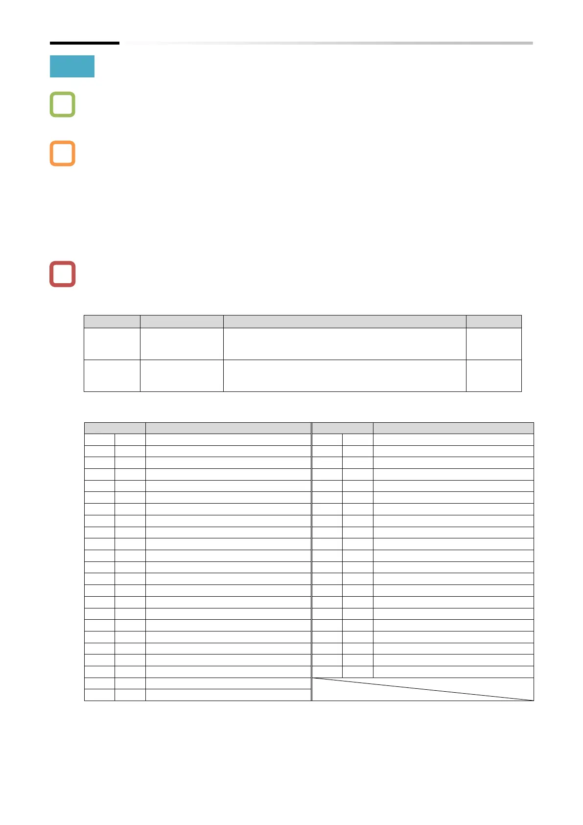
2nd-motor control [SET]:
Turn this function on to switch to the second control
parameter.
2nd-motor control is selected [SETM]:
After [SET] is turned on, switching to the second
control parameter turns this signal on.
◼ List of parameters switched by turning [SET] on/off
Acceleration time 1 setting or monitor
Deceleration time 1 setting or monitor
Electronic thermal characteristics selection
Frequency input source selection
Overload restriction 1 mode selection
RUN command input source selection
Overload restriction 1 active level
Overload restriction 1 action time
Async. Motor constant selection
Torque boost mode selection
Manual torque boost value
Async. Motor number of poles
Manual torque boost peak speed
Async. Motor speed response
Async. Motor stabilization constant
Automatic torque boost voltage compensation gain
Automatic torque boost slip compensation gain
Async. Motor constant R1 (auto-tuning data)
Async. Motor constant R2 (auto-tuning data)
Async. Motor constant L (auto-tuning data)
Async. Motor constant I0 (auto-tuning data)
Accel/Decel change trigger selection
Async. Motor constant J (auto-tuning data)
Accel1 to Accel2 frequency transition point
Decel1 to Decel2 frequency transition point

 Loading...


