OM-258 267 Page 28
SECTION 9 − GMAW WELDING (MIG) GUIDELINES
Wire Feeder/
Power Source
Workpiece
Gun
Regulator/
Flowmeter
Gas
Shielding Gas
Work Clamp
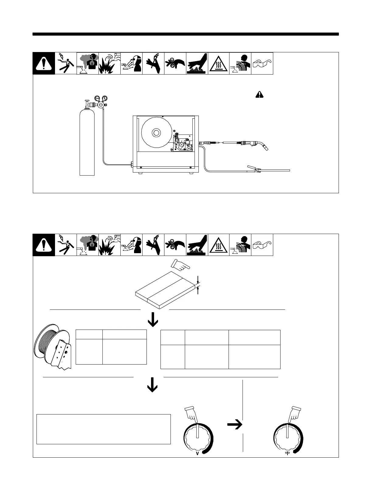
9-1. Typical GMAW (MIG) Process Connections
! Weld current can damage
electronic parts in vehicles.
Disconnect both battery
cables before welding on a
vehicle. Place work clamp as
close to the weld as possible.
GMAW1 2013−05 (GMAW Only) − Ref. 801 909-A
9-2. Typical GMAW (MIG) Process Control Settings
. These settings are guidelines only. Material and wire type, joint design, fitup, position, shielding gas, etc. affect settings. Test welds to be sure
they comply to specifications.
3.5 x 125 A = 437 ipm
2 x 125 A = 250 ipm
1.6 x 125 A = 200 ipm
30 − 90 A
40 − 145 A
50 − 180 A
Convert Material
Thickness to
Amperage (A)
Material thickness determines weld
parameters.
.035 in
Recommendation
Wire Speed
(Approx.)
1/8 or 0.125 in.
(0.001 in. = 1 ampere)
0.125 in. = 125 A
Wire Size Amperage Range
0.023 in.
0.030 in.
0.035 in.
Select Wire Size
Wire
Size
0.023 in.
0.030 in.
0.035 in.
3.5 in. per ampere
2 in. per ampere
1.6 in. per ampere
Select Wire Speed (Amperage)
125 A based on 1/8 in.
material thickness
ipm = inches per minute
Low voltage: wire stubs into work
High voltage: arc is unstable (spatter)
Set voltage midway between high/low voltage
Select Voltage
Voltage controls height and
width of weld bead.
Wire speed (amperage) controls weld
penetration (wire speed = burn-off rate)

 Loading...