EasyManua.ls Logo

Hobart Champion 145 User Manual

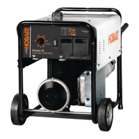
Hobart Champion 145
48 pages
To Next Page IconTo Next Page
Page #1 background imageLoading...
Page #1 background image
File: Engine Drive
Champion 145
www.HobartWelders.com
Description
OM-250 200B 201208
Processes
)
Stick (SMAW) Welding
Engine Driven Welding Generator

Table of Contents

Questions and Answers:

Hobart Champion 145 Specifications

General IconGeneral
Welding Amperage Range40-145 Amps
Fuel TypeGasoline
Welding ProcessesStick (SMAW)
Frequency60 Hz
Generator Power Output4, 500 Watts
Rated Output30% Duty Cycle
Open Circuit Voltage80 Volts
Electrode Sizes1/16" - 5/32"

Summary

SECTION 1 - SAFETY PRECAUTIONS - READ BEFORE USING

1-1. Symbol Usage

Explains warning symbols used in the manual to indicate hazards.

1-2. Arc Welding Hazards

Details hazards associated with arc welding processes and required protective measures.

1-3. Engine Hazards

Covers potential dangers related to the engine, including battery, fuel, and moving parts.

1-4. Compressed Air Hazards

Outlines risks associated with compressed air equipment and systems.

1-5. Additional Symbols For Installation, Operation, And Maintenance

Introduces symbols for installation, operation, maintenance, and associated hazards.

1-6. California Proposition 65 Warnings

Lists chemicals known to cause cancer or birth defects per California law.

1-7. Principal Safety Standards

References key safety standards and guidelines for welding and allied processes.

1-8. EMF Information

Explains electromagnetic fields and precautions for personnel with medical implants.

SECTION 2 – SAFETY GUIDELINES - READ BEFORE USE

2-1. Symbol Meaning

Defines danger and warning symbols and their meanings.

2-2. Arc Welding Hazards

Details arc welding hazards like electric shock, and precautions.

2-3. Engine Hazards

Covers engine-specific hazards such as battery explosion, fuel issues, and moving parts.

2-4. Compressed Air Hazards

Explains hazards related to compressed air, including inhalation and pressure risks.

2-5. Additional Hazards Related to Installation, Operation, and Maintenance

Discusses hazards like fire, explosion, falling equipment, and overheating.

2-6. California Proposition 65 Warnings

Lists chemicals in products known to cause cancer or birth defects.

2-7. Principal Safety Standards

Provides references for key safety standards related to welding and allied processes.

2-8. Information Regarding EMC

Explains electromagnetic compatibility and potential interference with medical devices.

SECTION 3 – DEFINITIONS

3-1. Additional Safety Symbols And Definitions

Presents additional safety symbols and their meanings.

3-2. Miscellaneous Symbol Definitions

Defines various symbols used for controls and indicators on the equipment.

SECTION 4 – SPECIFICATIONS

4-1. Weld, Power, And Engine Specifications

Details the technical specifications for welding, power output, and engine.

4-2. Dimensions, Weights, And Operating Angles

Lists the physical dimensions, weight, and safe operating angles for the unit.

4-3. Fuel Consumption

Shows a graph illustrating fuel consumption based on DC weld amperes.

4-4. Duty Cycle

Explains duty cycle and provides a chart relating weld amperes to duty cycle percentage.

4-5. Generator Power Curve

Displays AC power curves showing generator output in amperes at different voltages.

4-6. Volt-Ampere Curves

Illustrates the minimum and maximum voltage and amperage output capabilities.

SECTION 5 - INSTALLATION

5-1. Serial Number And Rating Label Location

Indicates where to find the serial number and rating label on the stator.

5-2. Installing Welding Generator

Provides guidelines for installing the welding generator, including airflow and location.

5-3. Grounding Generator To Truck Or Trailer Frame

Explains the procedure for grounding the generator frame to a vehicle frame.

5-4. Engine Prestart Checks

Details essential checks to perform on the engine before starting, including fuel and oil levels.

5-5. Weld Output Terminals

Identifies the weld output terminals and their purpose for connecting cables.

5-6. Connecting Weld Output Cables

Guides on how to correctly connect weld output cables to the terminals for safety and performance.

5-7. Selecting Weld Cable Sizes

Provides a chart to help select appropriate weld cable sizes based on amperage and cable length.

SECTION 6 – OPERATING THE WELDING GENERATOR

6-1. Controls (See Section 6-2)

Identifies the main controls on the welding generator unit.

6-2. Description Of Controls (See Section 6-1)

Provides detailed descriptions of each control and their functions.

6-3. Amperage Selection Table For Stick (SMAW) Electrodes

Offers a table to select the correct amperage for different stick welding electrodes.

6-4. Cold Weather Operation

Advises on operating the generator in cold weather conditions and potential issues.

SECTION 7 – OPERATING AUXILIARY EQUIPMENT

7-1. Generator Power Panel Receptacles

Describes the different power receptacles available on the generator panel and their ratings.

7-2. GFCI Receptacle Information, Resetting And Testing

Explains GFCI receptacles, how to test, reset, and troubleshoot them.

SECTION 8 – MAINTENANCE

8-1. Routine Maintenance

Outlines routine maintenance tasks and their recommended intervals.

8-2. Servicing Air Cleaner

Provides instructions for cleaning and servicing the air cleaner element and precleaner.

SECTION 9 – TROUBLESHOOTING

9-1. Troubleshooting

Offers solutions for common welding and generator power problems.

SECTION 10 - PARTS LIST

10-1. Recommended Spare Parts

Lists recommended spare parts for the welding generator unit.

SECTION 11 – ELECTRICAL DIAGRAMS

Circuit Diagram For Welding Generator

Presents the electrical circuit diagram for the welding generator unit.

SECTION 12 – GENERATOR POWER GUIDELINES

12-1. Selecting Equipment

Guides on selecting appropriate electrical equipment for use with the generator.

12-2. Grounding Generator To Truck Or Trailer Frame

Details the procedure for grounding the generator to a vehicle frame.

12-3. Grounding When Supplying Building Systems

Explains how to ground the generator for supplying power to building systems.

12-4. How Much Power Does Equipment Require?

Provides guidance on calculating power requirements for various equipment.

12-5. Approximate Power Requirements For Industrial Motors

Lists power requirements for different types of industrial motors.

12-6. Approximate Power Requirements For Farm/Home Equipment

Lists power requirements for common farm and home equipment.

12-7. Approximate Power Requirements For Contractor Equipment

Lists power requirements for various contractor equipment.

12-8. Power Required To Start Motor

Explains how to determine the starting power requirements for single-phase motors.

12-9. How Much Power Can Generator Supply?

Advises on generator output limits and starting non-resistive loads.

12-10. Typical Connections To Supply Standby Power

Illustrates typical connections for supplying standby power using the generator.

12-11. Selecting Extension Cord (Use Shortest Cord Possible)

Provides charts for selecting appropriate extension cords based on load and length.

SECTION 13 – STICK WELDING (SMAW) GUIDELINES

13-1. Stick Welding Procedure

Details the step-by-step procedure for performing stick welding (SMAW).

13-2. Electrode and Amperage Selection Chart

Presents a chart for selecting electrodes and corresponding amperage settings.

13-3. Striking an Arc

Explains two techniques for striking an arc: scratch and tapping.

13-4. Positioning Electrode Holder

Shows correct positioning of the electrode holder for groove and fillet welds.

13-5. Poor Weld Bead Characteristics

Illustrates common weld bead defects and their causes.

13-6. Good Weld Bead Characteristics

Shows examples of good weld beads and their characteristics.

13-7. Conditions That Affect Weld Bead Shape

Explains how electrode angle, arc length, and travel speed affect weld bead shape.

13-8. Electrode Movement During Welding

Demonstrates stringer bead and weave bead techniques for electrode movement.

13-9. Groove (Butt) Joints

Describes different types of groove (butt) joints for welding.

13-10. Lap Joint

Explains the procedure for performing a lap joint weld.

13-11. Tee Joint

Details the procedure for performing a tee joint weld.

13-12. Weld Test

Describes how to perform a weld test to check for strength and integrity.

13-13. Troubleshooting

Provides solutions for weld defects like porosity, spatter, and incomplete fusion.

Warranty

Related product manuals