How to decrease high weld output on my Hobart Champion 145?
- BBrittany HarperSep 12, 2025
If your Hobart Welding System is producing high weld output, check the amperage control setting.
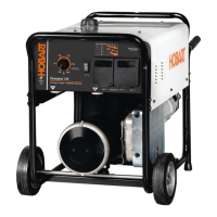
How to decrease high weld output on my Hobart Champion 145?
If your Hobart Welding System is producing high weld output, check the amperage control setting.
What to do if my Hobart Champion 145 has low output at generator power ac receptacles?
If your Hobart Welding System has low output at the generator power AC receptacles, check the amperage control setting and set it to Max for generator power. If the issue persists, have a Factory Authorized Service Agent check the engine speed, and adjust if necessary.
| Welding Amperage Range | 40-145 Amps |
|---|---|
| Fuel Type | Gasoline |
| Welding Processes | Stick (SMAW) |
| Frequency | 60 Hz |
| Generator Power Output | 4, 500 Watts |
| Rated Output | 30% Duty Cycle |
| Open Circuit Voltage | 80 Volts |
| Electrode Sizes | 1/16" - 5/32" |
Explains warning symbols used in the manual to indicate hazards.
Details hazards associated with arc welding processes and required protective measures.
Covers potential dangers related to the engine, including battery, fuel, and moving parts.
Outlines risks associated with compressed air equipment and systems.
Introduces symbols for installation, operation, maintenance, and associated hazards.
Lists chemicals known to cause cancer or birth defects per California law.
References key safety standards and guidelines for welding and allied processes.
Explains electromagnetic fields and precautions for personnel with medical implants.
Defines danger and warning symbols and their meanings.
Details arc welding hazards like electric shock, and precautions.
Covers engine-specific hazards such as battery explosion, fuel issues, and moving parts.
Explains hazards related to compressed air, including inhalation and pressure risks.
Discusses hazards like fire, explosion, falling equipment, and overheating.
Lists chemicals in products known to cause cancer or birth defects.
Provides references for key safety standards related to welding and allied processes.
Explains electromagnetic compatibility and potential interference with medical devices.
Presents additional safety symbols and their meanings.
Defines various symbols used for controls and indicators on the equipment.
Details the technical specifications for welding, power output, and engine.
Lists the physical dimensions, weight, and safe operating angles for the unit.
Shows a graph illustrating fuel consumption based on DC weld amperes.
Explains duty cycle and provides a chart relating weld amperes to duty cycle percentage.
Displays AC power curves showing generator output in amperes at different voltages.
Illustrates the minimum and maximum voltage and amperage output capabilities.
Indicates where to find the serial number and rating label on the stator.
Provides guidelines for installing the welding generator, including airflow and location.
Explains the procedure for grounding the generator frame to a vehicle frame.
Details essential checks to perform on the engine before starting, including fuel and oil levels.
Identifies the weld output terminals and their purpose for connecting cables.
Guides on how to correctly connect weld output cables to the terminals for safety and performance.
Provides a chart to help select appropriate weld cable sizes based on amperage and cable length.
Identifies the main controls on the welding generator unit.
Provides detailed descriptions of each control and their functions.
Offers a table to select the correct amperage for different stick welding electrodes.
Advises on operating the generator in cold weather conditions and potential issues.
Describes the different power receptacles available on the generator panel and their ratings.
Explains GFCI receptacles, how to test, reset, and troubleshoot them.
Outlines routine maintenance tasks and their recommended intervals.
Provides instructions for cleaning and servicing the air cleaner element and precleaner.
Offers solutions for common welding and generator power problems.
Lists recommended spare parts for the welding generator unit.
Presents the electrical circuit diagram for the welding generator unit.
Guides on selecting appropriate electrical equipment for use with the generator.
Details the procedure for grounding the generator to a vehicle frame.
Explains how to ground the generator for supplying power to building systems.
Provides guidance on calculating power requirements for various equipment.
Lists power requirements for different types of industrial motors.
Lists power requirements for common farm and home equipment.
Lists power requirements for various contractor equipment.
Explains how to determine the starting power requirements for single-phase motors.
Advises on generator output limits and starting non-resistive loads.
Illustrates typical connections for supplying standby power using the generator.
Provides charts for selecting appropriate extension cords based on load and length.
Details the step-by-step procedure for performing stick welding (SMAW).
Presents a chart for selecting electrodes and corresponding amperage settings.
Explains two techniques for striking an arc: scratch and tapping.
Shows correct positioning of the electrode holder for groove and fillet welds.
Illustrates common weld bead defects and their causes.
Shows examples of good weld beads and their characteristics.
Explains how electrode angle, arc length, and travel speed affect weld bead shape.
Demonstrates stringer bead and weave bead techniques for electrode movement.
Describes different types of groove (butt) joints for welding.
Explains the procedure for performing a lap joint weld.
Details the procedure for performing a tee joint weld.
Describes how to perform a weld test to check for strength and integrity.
Provides solutions for weld defects like porosity, spatter, and incomplete fusion.

