Do you have a question about the Hobart IronMan 230 and is the answer not in the manual?
Indicates possible hazards and provides warnings for safe operation.
Details potential dangers associated with arc welding processes and equipment.
Covers symbols for hazards like fire, falling equipment, and static discharge.
Provides warnings about chemicals in fumes and batteries known to cause birth defects or cancer.
Lists key industry standards for welding safety and practices.
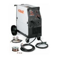
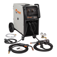
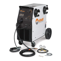
Details technical specifications including rated output, input, wire types, and dimensions.
Explains duty cycle limitations and how to prevent overheating.
Provides step-by-step instructions for connecting the welding gun to the unit.
Guides on connecting the shielding gas cylinder, regulator, and hose.
Covers proper unit placement and electrical input power connection procedures.
Step-by-step guide for loading and threading welding wire through the drive assembly.
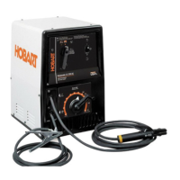
Identifies and explains the function of the machine's control panel elements.
Provides recommended settings for various wire types, gases, and metal thicknesses.
Outlines regular checks and maintenance tasks for the welding equipment.
Lists common welding problems and their corrective actions.
Addresses issues related to wire feeding and gun operation.
Illustrates the standard setup for MIG welding processes.
Offers guidance on setting voltage, amperage, and wire speed for MIG welding.
Identifies causes and solutions for excessive spatter during welding.
Explains how to resolve porosity issues in weld metal.
Details common causes and remedies for insufficient weld penetration.
| Weldable Materials | Steel, Stainless Steel, Aluminum |
|---|---|
| Input Voltage | 230 V |
| Input Phase | 1 Phase |
| Duty Cycle | 30% @ 230 A |
| Welding Processes | MIG (GMAW), Flux-Cored (FCAW) |
| Wire Feed Speed Range | 50-700 IPM |