2
FireNET 4127 I & O Manual v1.90 UL
Table of Contents
Table of Contents ........................................................................................................................... 2
Prefix – Programming Compliance with UL864 9
th
Edition ........................................................ 7
Section 1 – Introduction
......................................................................................................................................................... 8
1.1 Basic Features .................................................................................................... 8
1.2 System Devices and Equipment ......................................................................... 9
1.2A System Devices BOSCH ................................................................................ 11
1.2B System Devices Silent Knight ........................................................................ 12
1.2.1 System Replacement Parts ......................................................................... 13
1.3 Limitations of Fire Alarm Systems .................................................................... 14
1.4 Agency Listings, Approvals, Requirements ...................................................... 17
1.4.1 Federal Communications Commission (FCC) .............................................. 17
1.4.2 Underwriters Laboratories (UL) .................................................................... 17
1.4.3 National Fire Protection Association (NFPA) ............................................... 17
Section 2 – Control Panel Installation
....................................................................................................................................................... 18
2.1 What’s in the Box? ............................................................................................ 18
2.2 Environmental Specifications ............................................................................ 18
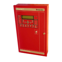
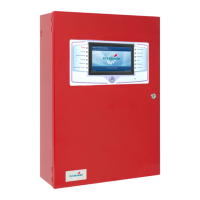
2.3 Control Panel Layout ........................................................................................ 19
2.3.1 Front Panel Layout, Standard Build ............................................................. 19
2.3.2 Front Panel Layout, Denver Door Build ....................................................... 20
2.3.3 Control Panel Annunciator, Control Unit and Power Supply Layout ............ 21
2.4 Mounting the Control Panel .............................................................................. 22
2.5 Wiring Specifications ........................................................................................ 22
2.5.1 Suggested Routing of AC Power ................................................................. 23
2.6 Battery Calculations .......................................................................................... 24
2.7 Electrical Ratings .............................................................................................. 27
2.8 Specifications ................................................................................................... 30
Section 3 - Power Supply and Main Control Unit Connections
....................................................................................................................................................... 31
3.1 AC Power Connection ...................................................................................... 31
3.2 Battery Connection ........................................................................................... 31
3.3 Auxiliary Power Connection .............................................................................. 32
3.4 Notification Appliance Circuit Connection ......................................................... 34
3.5 Voltage Routing and Relay Output Connection ................................................ 35
3.5.1 Voltage Routing Outputs .............................................................................. 35
3.5.2 Relay Outputs .............................................................................................. 36
3.6 Digital Input Connection .................................................................................... 37
3.7 Using a Printer .................................................................................................. 38
Section 4 – Expander Board Installation
....................................................................................................................................................... 39
 Loading...