©/TM
2023 UnityLab Corp. All rights reserved. | 1211
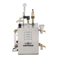
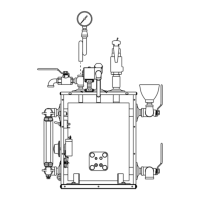
5.4 REPLACING THE GAUGE SIGHT GLASS
1. Turn off power to the boiler by pulling the plug or turning off power at the
branch switch or the circuit breaker.
2. Allow the boiler to cool to zero pressure.
3. Drain the water from the boiler. Leave the drain valve open.
4. Remove the Sight Glass Guard.
5. Remove the ttings that hold the glass in position. Top and Bottom nuts hold
the glass in position.
6. Replace the gauge glass. Do not over tighten. Always use new seals when
replacing the gauge glass.
7. Check for straight alignment of gauge glass. Brass ttings should not be
touching glass, realign if necessary.
8. Reinstall Sight Glass Guard.
9. Check for leaks during initial operation.
5.5 REPLACING THE HEATING ELEMENT
(To be performed by a licensed electrician)
1. Turn off the power to the boiler by pulling the plug or turning off the power at
the branch switch or the circuit breaker.
2. For models with manually operated steam outlet valves, allow the boiler to
cool to zero pressure. Test by opening steam outlet. For models with pedal
controlled steam outlet valves, turn power on, turn thermostat to off. Allow
boiler to cool to zero pressure. Test by stepping on pedal. At zero pressure,
turn power off at branch switch or circuit breaker or pull the plug.
3. Drain the water from boiler. Leave drain valve open.
4. Remove the front cover to the boiler enclosure.
5. Disconnect the wires from the heating element.
6. Remove the bolts on the heating element.
7. Remove “old” heating element.
8. Seal the gasket on both sides of the “new” heating element with a gasket
sealer. Use a “new” gasket.
NOTE: FOR MODELS WITH THERMOSTATIC CONTROL AND THERMOSTATIC RESET
(THERMODISC), IT IS IMPERATIVE TO INSTALL THE NEW ELEMENT WITH THE
THERMOWELL TUBES IN THE TOP POSITION.
9. Insert the “new” heating element, and tighten the bolts. If generator has
the thermostatic control/thermostatic reset (thermodisc), install sensing
probe(s) in heating element thermowell tubes.
10. Rewire the heating element.
11. Fill the boiler to the normal level, and CHECK FOR ANY LEAKS.
12. Power the boiler and allow the boiler to come up to pressure. CHECK FOR ANY
LEAKS.
13. Remount the front of the boiler enclosure.
14. Periodically, check for leaks during rst few days after installing new element.
5.6 REPLACING THE LOW WATER SWITCH
(To be performed by a licensed electrician)
1. Turn off the power to the boiler by pulling the plug or turning off the power at
the branch switch or the circuit breaker.
2. Allow the boiler to cool to zero pressure. Drain the boiler. Leave the valve
open.
3. Disconnect the wires from the Low Water Switch.
4. Remove the screws holding the Low Water Switch to the Cover. Save the
screws, they will be re-used.
5. Remove sensing probe from heating element.
6. Remove “old” Low Water Switch.
7. Re-attach the “new” Low Water Switch to the cover using the screws.
8. Insert sensing probe into the heating element. The sensing probe may not go
in all the way. This is normal. Insure that the sensing tube is bent slightly up
and out of the way of the heating element electric connections. Do not kink
the capillary tube.
9. Rewire the Low Water Switch.
10. Fill the boiler to the normal level.
11. Power the boiler and allow the boiler to come up to pressure. If the boiler
does not heat, push the reset button in the center of the switch to reset the
Low Water Switch.
5.7 REPLACING THE ELECTRIC FOOT SWITCH AND/OR CORD
(To be performed by a licensed electrician)
For Models: JEL-3, JEL-4, JEL-6
1. Turn off the power to the boiler by pulling the plug or turning off the power at
the branch switch or the circuit breaker.
2. Allow the boiler to cool to zero pressure. Drain the boiler. Leave the valve
open.
3. Remove the front cover to the boiler enclosure.
4. Remove the top cover of the foot switch.