7
Adres producenta/ Adresse des Herstellers/ Manufacturer’s Address/ Адрес производителя
GTV Poland Sp. z o.o. Sp. k., ul. Przejazdowa 21, 05-800 Pruszków
3. ELECTRICAL SYMBOLS
Direct Current DC Continuity test
Alternating Current AC
˚C
Celcius
Direct or alternating
current DC/AC
AUTO
Automatic range selection
Important security
information.
Compliant with
the European Union Directive.
High voltage can occur. Double insulation
Ground
EF
Non-contact voltage measurement
Low battery Flashlight
Diode Non-contact frequency measurement
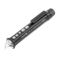
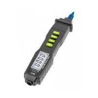
4. PANEL DESCRIPTION
1
14
13
5
9
10
2
3
4
6
12
11
8
7
1. Jaws of the meter
2. Flashlight
3. Alarm indicator
The indicator lights up when the meter detects a live wire.
4. Trigger
Press to open the jaws. When you release the trigger, the jaws will close again.
5. Functional / rotary switch
With this switch you can select the function and range.
6. Backlight button
Press the button, the backlight is on. Pressing again turns the backlight off .
7. Selection button
Press this button to select
, or V when the function switch is set to the appropriate range
position.
8. MAX button
Press this button to display the maximum and minimum values for the current measurement.
9. Press the button and the fl ashlight
press this button, the LCD display will show the last reading and „H” symbol will appear until you
press it again. Data storage will be cancelled automatically when the function switch is turned.
Press the button longer than 2 seconds, the fl ashlight is on, press the button again for 2 seconds.
The fl ashlight is off .
10. Range button
Press this button to select a range suitable for testing. for example, item 2 / 20A.
11. Display
3/5/6 digital LCD display with a maximum reading of 5999.
12. COM socket
13. INPUT socket
High insulation resistance input for all voltages, resistance and continuity and temperature.
14. NCV Measurement
It senses a strong electric fi eld, illuminates the NCV indicator LED.