6
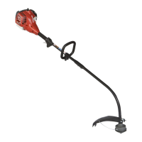
INSTRUCCIONES PARA EL
ENSAMBLAJE:
INSTALACION DE LA EMPUÑADURA
EN LA MANGA DEL EJE DEL
MOTOR
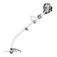
• Mantenga las dos abrazaderas (A) firmemente
en posición de manera que la agarradera (B)
quede situada a la izquierda del usuario.
• Introduzca el extremo de la agarradera entre las
abrazaderas.
• Alinee los orificios de los tornillos e introduzca el
tornillo largo (C) (1/4-20 x 1 1/2") por el lado de la
agarradera.
• Coloque el tornillo corto (D) (1/4-20 x 1") a través
del lado opuesto de la abrazadera. Install flat
washers (E), lock washers (F) and hex nuts (G)
to hold the assembly in place.
• Una vez que haya completado el ensamblaje,
ajuste la agarradera en una posición que le
resulte cómoda. Para fijarla, apriete primero el
tornillo largo y después el corto. Monte la correa
de sujeción (H) en la abrazadera con enganche
(I) y asústela siguiendo.
NOTA: Este producto incorpora una cabeza
de cuerda. Lea las instrucciones sobre
el método indicado para convertir la
unidad al uso con cuchilla.
PREPARACION PARA EL USOPRÉPARATION À L’EMPLOI
INSTRUCTIONS DE MONTAGE :
CARTER ENTRE LA POIGNÉE ET
L’AXE D’ENTRAÎNEMENT
• Maintenir fermement les deux colliers (A) en
position sur le carter d’axe d’entraînement pour
que la poignée (B) soit à la gauche de l’opérateur.
• Insérer l’extrémité de la poignée entre les colliers.
• Aligner les trous de vis et pousser la vis longue
(C) (1/4-20 x 1-1/2”) dans le côté de la poignée.
• Enfoncer la vis courte (D) (1/4-20 x 1”) dans le
côté opposé du collier. Install flat washers (E),
lock washers (F) and hex nuts (G) to hold the
assembly in place.
• Après l’assemblage, régler la poignée à une
position confortable et serrer d’abord la vis
longue et ensuite la courte. Accrocher la sangle
de confort (H) au crochet (I) et la régler en
suivant.
REMARQUE - Ce produit est livré assemblé
avec une tête pour fil. Voir les
instructions pour la conversion
avec lame.
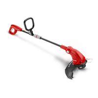
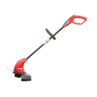
ASSEMBLY INSTRUCTIONS:
HANDLEBAR TO DRIVE SHAFT
HOUSING
• Hold the two clamps (A) snugly in position on
the drive shaft housing so that handle (B) will be
located to the operator's left.
• Insert the end of the handle between the clamps.
• Align the bolt holes and push the long bolt (C)
(1/4-20 x 1 1/2") through the handle side.
• Place short bolt (D) (1/4-20 x 1") through oppo-
site side of clamp. Install flat washers (E), lock
washers (F) and hex nuts (G) to hold the assem-
bly in place.
• After assembly is complete, adjust the handle
to a comfortable position and tighten first the
long bolt and then the short bolt. Connect
comfort strap (H) to hanger bracket (I) and
adjust.
NOTE: This product comes assembled with
a stringhead. See instructions for
conversion to blade unit.
PREPARING FOR USE
B
A
C
D
G
F
E
H
I
 Loading...