Do you have a question about the HONDA marine BF135 and is the answer not in the manual?
Controls for starting, stopping, and powering the engine, including the emergency stop switch.
Displays for engine speed, trim angle, voltage, and operating hours.
Switch for adjusting outboard motor angle and position.
The central processor managing engine operations, diagnostics, and fuel/ignition timing.
Components like the starter motor, main relay, and fuses for electrical power.
Components responsible for fuel delivery and system power control.
Glossary of abbreviations used for engine sensors in the diagram.
Monitors critical engine parameters like position, temperature, and pressure.
Fuel injectors and ignition coils for precise combustion control.
Controls for VTEC, intake, and water separator systems.
Visual identification of various engine sensors on the outboard motor.
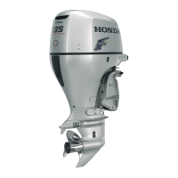
Visual identification of major engine components and parts on the outboard motor.
| Displacement | 2354cc |
|---|---|
| Full Throttle RPM Range | 5000-6000 RPM |
| Valve Train | SOHC |
| Ignition System | MicroComputer Programmed |
| Starting System | Electric |
| Lubrication System | Wet Sump |
| Cooling System | Water Cooled |
| Trim Range | -4° to +16° |
| Gear Ratio | 2.14:1 |
| Exhaust | Through Propeller |
| Gear Shift | F-N-R |
| Recommended Fuel | Unleaded Gasoline (86 Octane) |
| Bore & Stroke | 87 mm x 99 mm |
| Rated Power | 135 HP |
| Fuel Delivery | Programmed Fuel Injection |
| Propeller | Optional |
| Shaft Length | L (20 in), X (25 in) |
| Recommended Engine Oil | 10W-30 |
| Engine Type | 4-stroke |
| Dry Weight | 220 kg (485 lbs) - lightest version |