BF40AoBF50A
6)
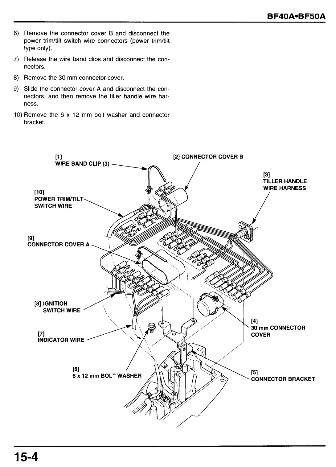
Remove the connector cover
B
and disconnect the
power trim/tilt switch wire connectors (power trim/tilt
type only).
7)
Release the wire band clips and disconnect the con-
nectors.
8)
Remove the
30
mm
connector cover.
9)
Slide the connector cover
A
and disconnect the con-
nectors, and then remove the tiller handle wire har-
ness.
10)
Remove the
6
x
12
mm
bolt washer and connector
bracket
.
[I1 [2] CONNECTOR COVER B
WIRE BAND CLIP
(3)
[31
TILLER HANDLE
WIRE HARNESS
11
01
POWER TRIM/TILT\
SWITCH WIRE
[91
CONNECTOR COVER
A
[8] IGNITION
SWITCH WIRE
’
[71
INDICATOR WIRE
161
6
x
12
mm
BOLT
\
141
30
mm
CONNECTOR
COVER
151
CONNECTOR BRACKET
 Loading...