40
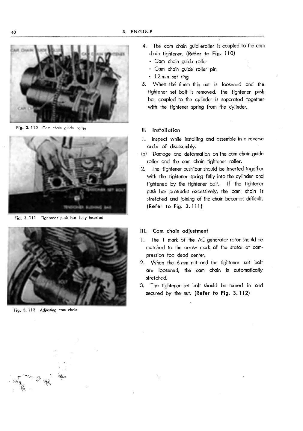
Fig.
3.
110
Cam chain guide railer
Fig.
3.
111
Tightener push
bar
fully inserted
Fig.
3.
112
Adjusting cam chain
3.
ENGINE
4. The cam chain guid eroller
is
coupled
to
the
cam
chain tightener. (Refer to Fig.
11
O)
• Cam chain guide roller
• Cam chain guide roller pin
•
12
mm
set
nng
5.
When
the 6
mm
thin
nut
is
loosened and the
tightener
set
bolt
is
removed, the tightener
push
bar coupled
to
the
cylinder
is
separated together
with the tightener spring from the cylinder.
II. Installation
1. Inspect while installing and
assemble
in a reverse
order
of
disassembly.
(a)
Damage and deformation on the
cam
chain .guide
roller and
the
cam
chain tightener roller.
2.
The
tightener push'bar should be inserted together
with the tightener spring fully into the cylinder and
tightened
by
the
tightener bolt.
If
the tightener
push
bar protrudes excessively, the
cam
chain
is
stretched and joining
of
the chain becomes difficult.
(Refer to Fig. 3. 111)
Ill.
Cam chain adjustment
1. The T
mark
of
the
AC
generator rotor
should
be
matched
to
the
arrow
mark
of
the stator at com-
pression top dead center.
2.
When
the 6
mm
nut
and the tightener set bolt
are loosened,
the
cam
chain
is
automatically
stretched.
3.
The tightener set bolt should be turned in and
secured
by
the
nut.
(Refer to
Fig.
3.
112)


 To Next Page