4. 3
STEERING
STEM
AND
HANDLEBAR LOCK
59
4.
3 Steering stem
and
handlebar lock
A. Construction
of
the steering stem
The
steering
stem
is
supported
by
8 X
32
hex bolts
on
the
front
cushion.
The
stem,
with the cone race
inside,
is
an
important unit for steeing since
it
is
a
rotation axis with the frame head pipe
as
the center.
To the steering
stem,
the steering absorber
is
installed
allowing
for
adjustment according
to
the status
of
road operation, and load.
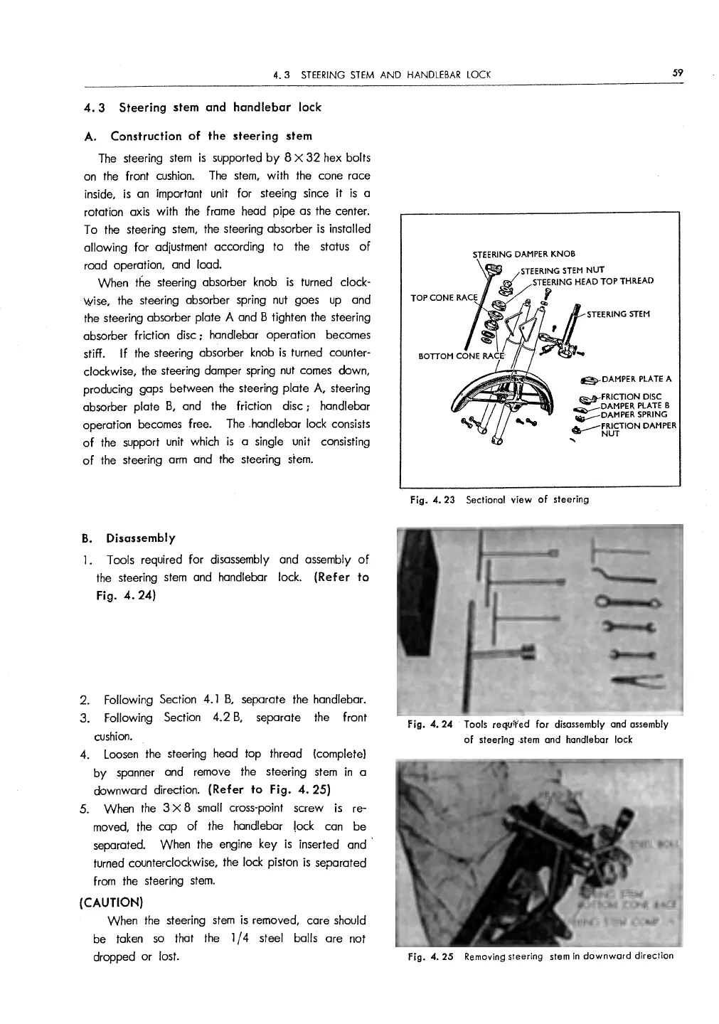
When the steering absorber knob
is
turned clock-
wise, the steering absorber spring nut goes
up
and
the steering absorber plate A and B tighten the steering
absorber friction disc : handlebar operation becomes
stiff.
If the steering absorber knob
is
turned counter-
clockwise, the steering damper spring nut comes down,
producing gaps between the steering plate A, steering
absorber plate
B,
and the friction disc : handlebar
operation becomes free.
The
handlebar lock consists
of
the support unit which
is
a single unit consisting
of
the steering
arm
and the steering
stem.
B.
Disassembly
l . Tools required
for
disassembly and assembly
of
the
steering
stem
and handlebar lock. (Refer to
Fig.
4.
24)
2.
3.
4.
Following
Section 4. l
B,
separate the handlebar.
Following
Section
4.2
B,
separate
the
front
cushion.
Loosen
the steering head top thread
(complete)
by
spanner and remove the steering
stem
in
a
downward direction.
(Refer to Fig.
4.
25)
5. When the 3 X 8
small
cross-point screw
is
re-
moved, the cap
of
the handlebar lock can be
separated. When the engine key
is
inserted and ·
turned counterclockwise, the lock piston
is
separated
from the steering
stem.
(CAUTION)
When the steering
stem
is
removed, care should
be taken
so
that the l / 4 steel balls are not
dropped
or
lost.
STEERING
DAMPER
KNOB
STEERING
STEM
@,-DAMPER
PLATE
A
~FRICTION
DISC
DAMPER
PLATE
B
-:==:DAMPER
SPRING
.---~~TION
DAMPER
...
Fig.
4.
23 Sectional view
of
steering
Fig. 4. 24 Tools requ.Yed for disassembly
and
assembly
of
steering -stem
and
handlebar lock
Fig. 4.
25
Removing steering stem
in
downward
direction


 To Next Page