70
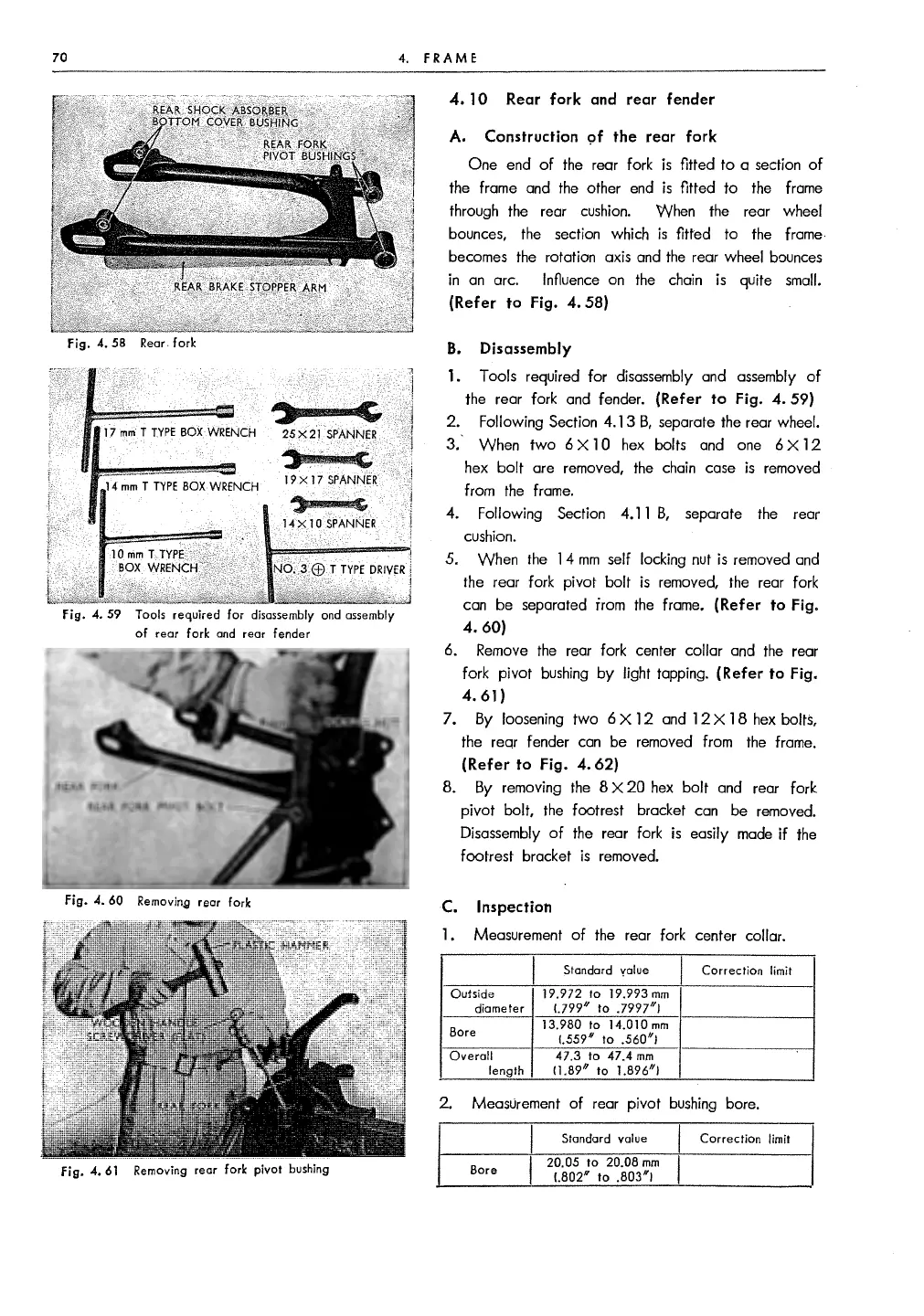
fig.
4.
58
Rear.
fork
,
25X21
SPANNER
14
mm
T
TYPE
BOX
WRENCH
19
X
17
SPANNER.
,
l
4X
10
SPANNER
Fig. 4. 59 Tools required
for
disassembly
ond
assembly
of
rear
fork
and
rear
fender
fig.
4. 60 Removing rear fork
Fig.
4.
61
Removing rear
fork
pivot
bushing
4.
f RAM E
:l
• j
j
]
4.
10
Rear
fork
and
rear fender
A, Construction
9f
the rear
fork
One end
of
the rear fork
is
fitted
to
a section
of
the frame and the other
end
is
fitted
to
the frame
through the rear
cushion.
When the rear wheel
bounces, the section which
is
fitted to the frame-
becomes the rotation axis and
the
rear wheel bounces
in
an
arc. Influence
on
the chain
is
quite
small.
(Refer to Fig. 4. 58)
B.
Disassembly
1. Tools required
for
disassembly and assembly
of
the rear fork and fender. (Refer to
Fig.
4.
59)
2.
Following Section
4.
13
B,
separate the rear wheel.
3, When
two
6 X 1 0
hex
baits and one 6 X
12
hex
bolt
are removed, the
chain
case
is
removed
from
the
frame.
4.
Following Section
4.11
B,
separate the rear
cushion.
5. When
the
1 4
mm
self locking nut
is
removed
and
the rear fork pivot bait
is
removed, the rear fork
can be separated irom
the
frame. (Refer to Fig.
4. 60)
6.
Remove
the
rear fork center collar and the rear
fork
pivot
bushing
by
light tapping. (Refer to
Fig.
4.61)
7. By loosening
two
6 X
12
and
12
X 1 8
hex
baits,
the rear fender
can
be removed from the frame.
(Refer
to Fig. 4.
62)
8.
By
removing
the
8 X
20
hex
bolt
and rear fork
pivot
bait, the footrest bracket can be removed.
Disassembly
of
the
rear
fork
is
easily
made
if
the
footrest bracket
is
removed.
C.
Inspection
l,
Measurement
of
the rear fork center collar.
I
Standard yolue
Correction
limit
Ou!side
19.972
lo
19.993
mm
diameter
t.799
11
to
.7997
11
1
Bore
13.980
to
14.010
mm
(.559
11
to
.560
11
!
Overall
47.3
lo
47.4
mm
length
(J.89h
to
J.896
11
I
2.
Measurement
of
rear pivot
bushing
bore.
Standard value
Correction
limit
Bore
20.05
to
20.08
mm
(.802
11
to
.803
11
1


 To Next Page