82
5.
ELECTRICAL
PARTS
Fig.
5.
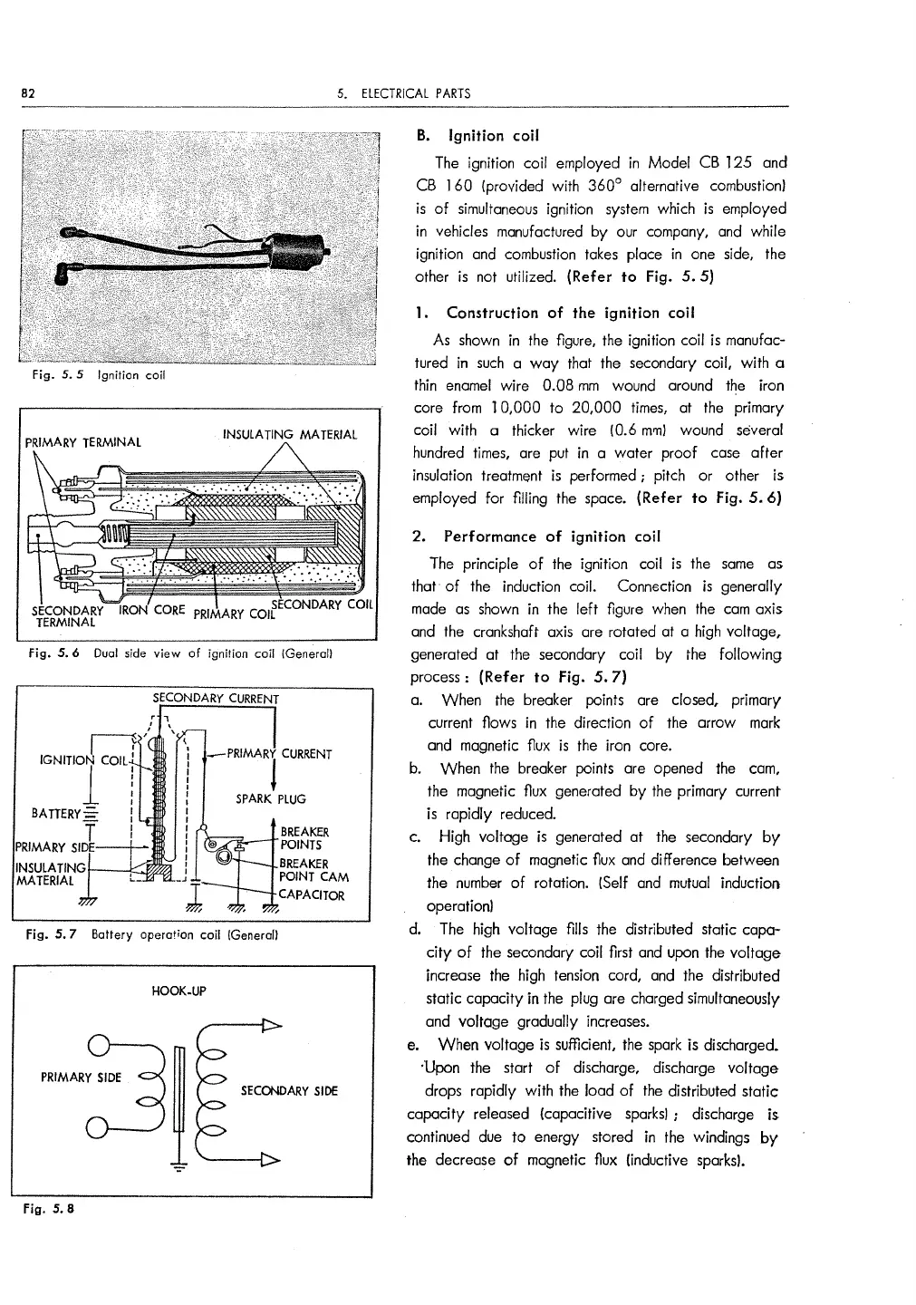
5 Ignition coil
fig.
5.
6
Dual
side
view
of
ignition coil (Generall
SECONDARY
CURRENT
-PRIMARY
CURRENT
J
SPARK
PLUG
BREAKER
.,.,,,___,.POINTS
BREAKER
POINT
CAM
CAPACITOR
Fig. 5. 7 Battery
operation
coil (General!
HOOK.UP
PRIMAA~
SECONDARY
SIDE
Fig. 5. 8
B.
Ignition coil
The
ignition coil employed
in
Model
CB
125
and
CB
l 60 {provided with
360°
alternative combustion)
is
of
simultaneous
ignition
system
which
is
employed
in
vehicles manufactured by our company,
and
while
ignition
and
combustion
takes
place
in
one side, the
other
is
not utilized. (Refer to Fig.
5.
5)
1. Construction
of
the ignition coil
As
shown
in
the figure, the ignition coil
is
manufac-
tured
in
such
a
way
that the secondary coil, with a
thin
enamel
wire 0.08
mm
wound around
the
iron
core from
10,000
to
20,000
times,
at
the
primary
coil with a thicker wire (0.6
mm}
wound several
hundred
times,
are put
in
a water proof
case
after
insulation
treatmE)nt
is
performed ; pitch or other is
employed for filling
the
space.
(Refer
to
Fig.
5.
6)
2. Performance
of
ignition coil
The
principle
of
the
ignition coil
is
the
same
as
that
of
the
induction coil. Connection
is
generally
made
as
shown
in the left figure
when
the
cam
axis
and
the
crankshaft axis are rotated at a
high
voltage,
generated at
the
secondary coil by
the
following
process: (Refer to Fig.
5.
7)
a.
When
the
breaker points are closed, primary
current flows
in
the
direction
of
the arrow
mark
and
magnetic
f1ux
is
the
iron core.
b. When
the
breaker points are opened
the
cam,
the magnetic flux generated
by
the
primary current
is
rapidly reduced.
c. High voltage
is
generated at
the
secondary by
the change
of
magnetic
f1ux
and
difference between
the
number
of
rotation. {Self
and
mutual
induction
operation)
d.
The
high voltage fills the distributed static capa-
city
of
the secondary coil first
and
upon
the
voltage
increase
the
high tension cord,
and
the distributed
static capacity in
the
plug are charged simultaneously
and voltage gradually increases.
El.
WhEln
voltage
is
sufficient,
the
spark
is discharged.
;Upon the start
of
discharge, discharge voltage
drops rapidly with
the
load
of
the
distributed static
capacity released (capacitive
sparks)
; discharge
is
continued
due
to
energy stored in
the
windings
by
the decrease
of
magnetic flux (inductive
sparks}.


 To Next Page