IV.
FRAME
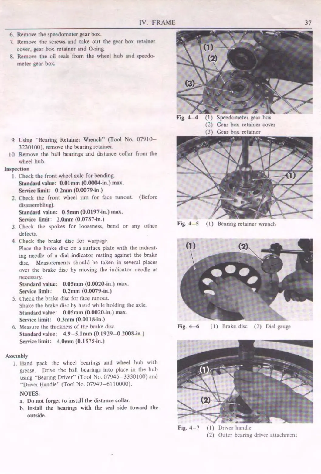
6.
Remove the speedometer gear box.
7.
Remove the screws
and
take out the
gear
box retainer
cover,
gear
box
retainer
and
O•ring.
8.
Remove the oil seals from the wheel hub and speedo-
meter gear box.
9.
Using "Bearing Retainer Wrench" (Tool No. 07910-
3230100), remove the bearing retainer.
JO.
Remove the ball bearings and distance collar from the
wheel hub.
Inspection
I. Check the front wheel axle
for
bending,
Standard value: 0.01mm (0.0004-in.)
max.
Sen'ice limit: 0.2mm (0.0079-in
.)
2. Check the front wheel rim for face runouL (Before
disassembling).
Standard value: 0.5mm (0.0197~n.) max.
Scn'ice limit: 2.0mm (0.0787,in.)
3.
Check the spokes for looseness, bend
or
any other
defects.
4.
Check the brake disc for warpage.
Place the brake disc on
a surface plate with the indicat•
ing needle
of
a dial indicator resting against the brake
disc.
Mea
sureme
nt,
should be taken in several places
over the brake disc
by
moving the indicator needle as
necessary.
Standard value: 0.05mm (0Jl020-in.) max.
Sen-ice limit: 0.2mm (0.0079-in.)
5.
Check the brake disc for face
runout
Shake the brake disc by hand
v.11ile
holding the axle.
Standard value: 0.05mm (0.0020-in.) max.
Service limit: 0.3mm (0.0118-in.)
6.
Measure the thickness
of
the brake disc.
Standard ,,aJue: 4.9 ,5
.l
mm (0.1929--0.2
008
-in.)
Sen'ice limit:
4.0mm
(0.1575-in.)
Assembly
I.
Uand pack
Lhe
wheel bearings and wheel huh with
grease. f)rivc the ball bearings into place in the huh
using "l.learing Driver" (Tool No. 07945 3330100) and
"Driver Handle'' (Tool No.
07949-6110000).
NOTES:
a. Do not forget
to
install
the
distance collar.
b. lostall
the
bearings with the seal side toward
the
out.side.
•
Fig.
4-4
{I)
Speedometer gear box
(2) Gear box retainer cover
(3)
Gear box retainer
Fig. 4- 5
(I)
Bearing retainer wrench
Fig.
4-6
(I)
Brake disc
(2)
Dial
gauge
Fig.
4-7
(I)
Driver handle
(2)
Outer bearing driver auachment
37
 Loading...