V.
ELECTRICAL
67
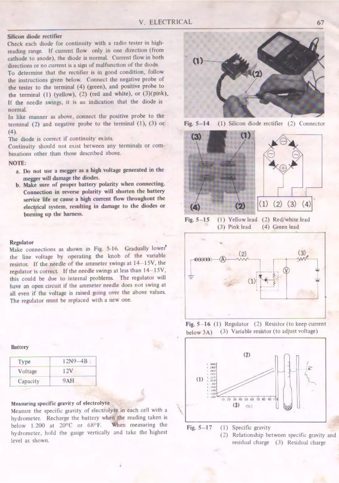
Silicon diode rectifier
Check each diode for continuity with a radio tester in high-
reading range.
If
currcm
flow only in
one
direction (from
cathode
10
anode), the diode
is
normal. Current llow in both
djrections
or
no
current
is
a
sign
of
malfuncticm
of
lhe
diode.
To
determin~ that the rectifier
is
ul good condition, follow
lhe uistructions given below. Connect the negative
probe
of
the tester
to
the terminal (
4)
(green), and p-0sitive prohe
to
the tenninal
(I)
(yellow), (2)
(red
and white),
or
(3)(pink).
lf
tl1e
needle swings,
it
is an indication lhal the diode
is
nonnal
In like manner
as
above, connect the positive probe
to
the
tenninal
(2) and negative probe
to
the temtinal
(I),
(3)
or
(4).
The diode
is
correct
if
continuity exists.
Continuily
should
not exist between any
terminals
or
com
4
binations
other
than those described above.
NOTE:
a.
Do
not
use a mcgger
as
a high voltage generated in
the
megger
will
damage
the
diodes.
b. Make sure
of
proper
battery
polarity when connecting.
Connection
in re,•er,;e polarity will
shorten
the
battery
service life
or
cause a high current
now
throughout the
electrical system, resulting in
damage
to
the
diodes
or
buming
up
the hamess.
Regulator
Make connections
as
shown ,n Fig. 5-16. Gradttally lower'
the line voltage
by
operating the knob
of
the variable
resistor.
If
the needle
of
the ammeter swings
at
14-ISV,
the
regulator
is
correcl
If
the needle swings
at
less than
14-JSV,
this could be due
to
internal problems. The regulator
will
have
an
open
circuit
if
the
ammeter
needle
docs
not
swing
at
all
even
if
(he vt)ltage
is
raised going over the above values.
The regulator must be replaced wilh a new one.
Battery
Type
Voltage
Capacity
,,,,~.
I
12V
1---
9
AH
Measuring specific gravity
of
electrolyte
Measure the specific grnvity
of
electrolyte in
each
cell with a
hydrometer. Recharge the
ballcry
when the reading taken
is
below l.
200
at
20°c
or
68°
F. When measuring the
hydrometer, hold the gauge vertically and take the highest
level as shown.
'
'\.
~
'f.
I
(1)-
1
-
..
Fig. S- 14 (1) Silicon diode rectifier (2) Connector
(1) (2) (3) (4)
Fig. 5-
15
(I)
Yellow lead (2) Red/white lead
(3)
Pink lead ( 4) Green lead
~
-7_
•
:
,.
Fig. 5 I 6
(I)
Regulator (2) Resistor (
to
keep current
below
3A) (3) Variable resistor
(to
adjust voltAge)
.
,~
"'
,.
.
"'
(l)
'
.~d.l
•.
~
(I
.
~
.
!1,!I
'
...
.
•
:i
v
"'
Fig.
S-17
m r~ n /
~
-\I
L
"'
~---1
"~
~,,,.,
,,
..,,.JI
(3)
,,
,;
ij
(I)
Specific gravity
(2) Relationship between specific gravity and
residual charge
(3)
Re
sidual charge
 Loading...