5.
TP
Sensor
Inspection
Replace the sensor unit with a known good one
(page 7-16).
Connect the sensor unit
5P
(Black) and
ECM
33P
(Black) connectors.
Erase the DTC's (page 4-12).
Turn the ignition switch ON.
Check the TP sensor with the MCS.
Is DTC 8-1 indicated?
YES - Replace the ECM with a known good one
and recheck.
NO - Faulty original sensor unit (TP sensor)
DTC (TP SENSOR HIGH
1.
TP Sensor System Inspection
Turn the ignition switch ON.
Check the TP sensor with the MCS with the throttle
fully closed.
Is about 5 Vindicated?
YES - GO TO STEP
3.
NO - GO TO STEP
2.
2.
TP Sensor Inspection
Check that the
TP
sensor voltage increases
continuously when moving the throttle from fully
closed to fully opened using the data list menu
of
the
MCS.
Does
the voltage increase continuously?
YES -
Intermittent failure
NO -
Replace the TP sensor (sensor unit) with a
known good one
and
recheck.
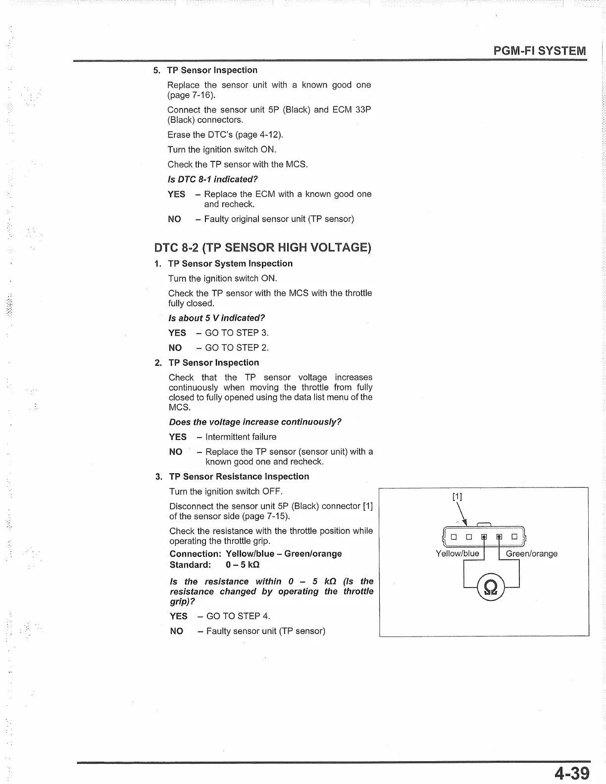
3.
TP Sensor Resistance Inspection
Turn the ignition switch OFF.
Disconnect the sensor unit
5P
(Black) connector
[1]
of
the sensor side (page 7-15).
Check the resistance with the throttle position while
operating the throttle grip.
Connection: Yellow/blue - Green/orange
Standard: 0 - 5
k!l
Is the resistance within O - 5
k!J.
(Is the
resistance changed
by
operating the throttle
grip)?
YES - GO TO STEP
4.
NO -
Faulty sensor unit (TP sensor)
PGM-FI SYSTEM
[1]
 Loading...