HE360 HUMIDIFIER AND INSTALLATION KIT
9 69-2629EF—09
3. The return duct is recommended, however the switch can also
be mounted to the supply duct.
4. Cut a 3/4-in. diameter hole in the duct within 10 feet of the
switch to ensure the provided tubing reaches the pressure tap
elbow.
5. Insert the black rubber gasket into the duct hole.
6. Connect the tubing to the tubing fitting elbow and insert the
tubing fitting elbow into the black rubber gasket.
7. Connect the other end of the tubing to the applicable pressure
connection on the switch.
e. Black connection if installed on the supply
f. Grey connection if installed on the return
g. Both grey and black if installed on both
IMPORTANT
With low-speed airflow or variable speed systems it is
recommended to run tubing to both the supply and return
ducts.
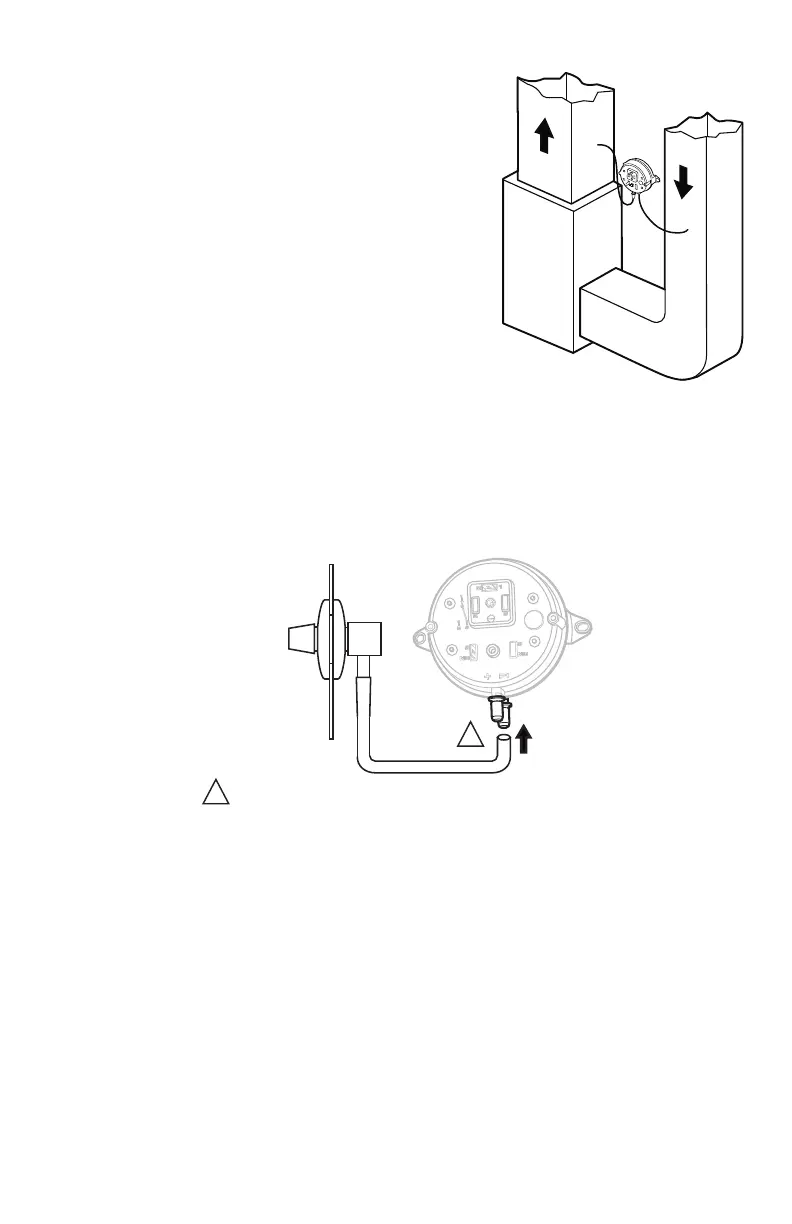
Fig. 10. Mounting the pressure switch.
Fig. 11. Install tubing.
8. You may cut the tubing to fit the connection length between the elbow fitting and switch. It is also
recommended to secure the hose to existing structures to avoid accidental disconnection.
M27303
A
B
SUPPLY DUCT INSTALL - AIR LINE ONLY TO TAP A,
CONNECTED TO THE + PORT ON THE AIR FLOW SWITCH
RETURN DUCT INSTALL - AIR LINE ONLY TO TAP B,
CONNECTED TO THE – PORT ON THE AIR FLOW SWITCH
SUPPLY/RETURN DUCT INSTALL - AIR LINE CONNECTED
TO BOTH THE + AND – PORTS ON THE AIR FLOW SWITCH
M27304A
INSIDE
OF DUCT
CONNECT TUBING TO + CONNECTION IF PRESSURE TAP IS
MOUNTED TO SUPPLY DUCT. CONNECT TO – IF PRESSURE
TAP IS MOUNTED TO RETURN DUCT.
1
1
 Loading...