Do you have a question about the Honeywell Home TH8321R1001 and is the answer not in the manual?
| Model Number | TH8321R1001 |
|---|---|
| Brand | Honeywell Home |
| Programmability | 7-Day Programmable |
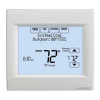
| Display Type | Touchscreen |
| Humidity Control | No |
| Mobile App | No |
| Voice Control | No |
| Product Type | Thermostat |
| Compatibility | Conventional and heat pump systems |
| Power Source | 24 VAC |
| Temperature Range | 40°F to 90°F |
Important instructions and warnings for product installation.
Procedure to find the password for installer options.
Steps for installing the Equipment Interface Module.
Instructions for wiring the 24 VAC common connection.
Steps for connecting power to the thermostat.
Instructions for wiring the thermostat directly to equipment.
Procedure to link thermostat to EIM during setup.
Steps to connect RedLINK accessories to the thermostat.
Lists and describes various installer setup options.
Details Installer Setup (ISU) options and their settings.
Steps to access installer tests for system verification.
Procedure to test heating, cooling, fan, and IAQ equipment.
Warning about bypassing compressor off-time during tests.
Optional outdoor temperature lockouts for heat pumps.
Steps to configure humidification control using RedLINK thermostats.
Steps to configure ventilation control for RedLINK thermostats.
Steps to configure dehumidification control for RedLINK thermostats.