Chapter 3 Installation and Test Operation
4 Pnet I/F Module 2MLL-PSRA, 2MLL-PMEA, 2MLL-PMEB User’s Guide R240
Honeywell January 2019
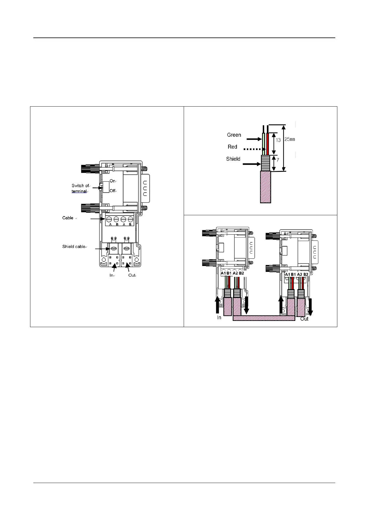
2) Pnet Connector structure and wiring method
(1) Input Line: green line is connected to A1, red line is connected to B1
(2) Output line: green line is connected to A2, red line is connected to B2
(3) Connect shield to clamp of shield
(4) In case of installing the connector at terminal, install the cable at A1, B1
 Loading...