9
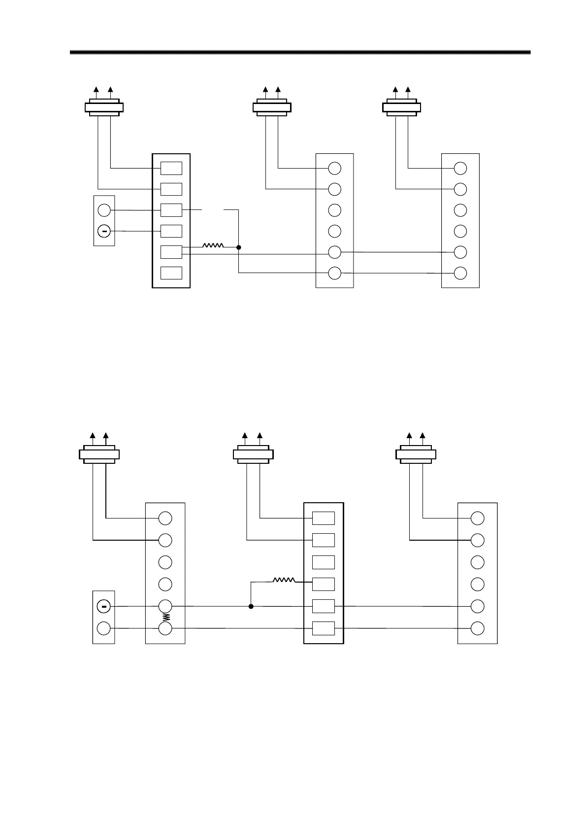
ML7984 Wiring
Fig. 12 Wiring for replacing the MASTER motor in 4-20 mA multiple-actuator application.
(Use Resistor Kit part # 272822)
Fig. 13 Wiring for replacing the SLAVE motor in 4-20 mA multiple-actuator application.
(Use Resistor Kit part # 272822)
C
B
W
R
C
B
W
R
T5
T6
C
B
W
R
**
*Previously clipped resistor
+
WWWW
R2=3 KΩ
R1=12 KΩ
L1 L1 L1L2 L2 L2
ML7984A3xxx
New Master
ML7984A3xxx
Slave
ML7984A3xxx
Slave
NOTE:
Turn power off before
setting the DIP switches
T5
T6 T6
T5
C
B
W
R
C
B
W
R
C
B
W
R
*
*Previously clipped resistor
+
R=133Ω
L1L1 L1L2L2 L2
ML7984A3xxx
New Slave
ML7984A3xxx
Slave
ML7984A3xxx
Slave
Factory installed -54.9Ω
NOTE:
Turn power off before
setting the DIP switches
T5
T6
T5
T6
T5
T6

 Loading...