Do you have a question about the Honeywell MB-Secure 4000 and is the answer not in the manual?
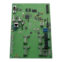
Details the main circuit board, its components, jumpers, and DIP switches.
Lists compatible reader types that can be directly connected to the Modulbus/RS-485 controller.
Introduces various optional modules that can extend the functionality of the control panel.
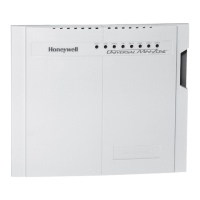
Describes the MB-Secure Siren Module, its connections, and programming jumpers.
Details the AWUG DS 6700/DS 6750 automatic transmission devices and their connections.
Explains the AWUG DS 7700 automatic transmission device, its features, and connections.
Provides guidelines for the physical installation and mounting location of the control panel.
Covers the requirements and considerations for connecting the power supply and batteries.
Lists current consumption values for various control panel components and connected devices.
Explains how to calculate the required battery capacity for system backup.
Step-by-step guide to power up and initialize the control panel and system components.
Instructions for performing firmware updates on the control panel and connected devices.
Shows the detailed wiring diagram for the main computer/connection PCB.
| Brand | Honeywell |
|---|---|
| Model | MB-Secure 4000 |
| Category | Control Panel |
| Language | English |


