Do you have a question about the Honeywell MB-Secure 2000 and is the answer not in the manual?
Crucial safety guidelines and warnings for system installation and operation.
Lists available options like power supply units, modules, and transmission devices.
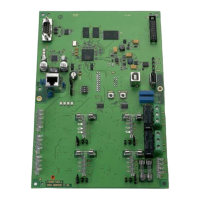
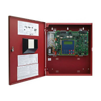
Detailed view and description of the main computer/connection PCB components.
Details various extension modules that can be connected to the control panel.
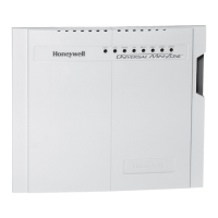
Describes the automatic transmission device with modem and Ethernet capabilities.
Details mains connection, fuses, FI switches, and battery requirements for VdS systems.
Table listing current consumption for various control panel components, detectors and users.
Guidelines for protecting against electromagnetic interference using shielded cables and grounding.
Covers software versions for evaluation units, transmission devices, and BUS-2 operating units.
Details on programming BUS-2 users via switches and their addresses.
Steps for initial electrical operation, including line checks and LED indicators.
Procedure for updating firmware using a USB stick, including important notes.
Details connections for the IK3 evaluation unit, including software version requirements.
Shows connection details for the computer/connection PCB to power supply, transmission device, and controllers.
| Brand | Honeywell |
|---|---|
| Model | MB-Secure 2000 |
| Category | Control Panel |
| Language | English |
