Installation Instructions MB-Secure 1000/2000/3000/4000/5000/6000 19
3 Installation
Also see brochure “Electrical installation of hazard detection devices " (no. P03061-15-000-XX).
3.1 Mounting
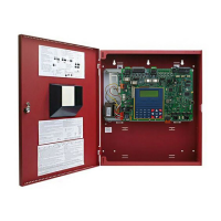
The device is intended for wall mounting. The housing (option) consists of a back panel and a detachable
housing rack with front door (not ZG20 and ZG4).
For installation, first attach the back panel without rack and front door at the appropriate location and install the
PCBs and power supply/charger units. After the PCBs are wired, the housing rack can be attached and screwed
onto the back panel.
The location where the control panel is installed should meet the following conditions:
* must be inside the protection zone
* must be within the internal areas of the building
* must be easily accessible
* must not be exposed to any unusual environmental conditions, e.g. aggressive vapors, high humidity etc.
* must be at eye level
* must not be visible from outside
* must be sturdy enough to ward off attempts to tear it off
* there must be sufficient distance to nearby machinery
* must be on the interior wall of the protection zone - intrusion monitoring may be necessary if installation is
possible only on the external wall
Lead-seal the screws after installing and placing into operation.
3.2 Power supply
The power supply must be connected to the mains via a separate fuse (meter box, sub-distribution). No loads
external to the system should be connected to this circuit. The power supply can also be connected to a circuit
meant exclusively for the internal lighting systems of the zones to be monitored.
If the operator’s mains circuit is equipped with a fault-current safety switch (FI switch), the power supply must be
assigned its own FI switch capable of carrying overload current.
The fuse and the FI switch should be located within the protection zone.
If the power supply of the intrusion detector control panel is not part of the control panel, it should be installed
(mutually screwed) right next to the control panel (without any gap). It must be impossible to reach the
connection lines without mechanical damaging the housing.
For intruder alarm systems with multiple power supply devices, fault signals from each power supply device
must be indicated on the intruder alarm control panel. A central indicator will suffice only if the individual power
supply units have their own fault indicator.
A battery room is permitted only if it is included in the monitoring.
The batteries provided with the power supply must be VdS-approved. If batteries are connected in parallel, only
the same type of batteries of the same age must be used.
If the mains fail, uninterrupted and unrestricted operation of the IDS must be ensured for a minimum of 60 hours
(VdS Class C) using batteries. Before these 60 hours elapse, the alarm signalling units should have an
operational capacity of at least 60 seconds. The battery capacity required must be determined when the IDS is
in detection-ready state by measuring the current consumption in the armed and disarmed state. In a disarmed
system, the power consumption of the fault display(s) and one detector group display, or 10% of the detector
group displays if there are more than 10 detector groups, must also be taken into account. Group displays that
can displayed only via a locking test key need not be considered. The higher current consumption in each case
is decisive in the design of the battery capacity.

 Loading...
