Installation Instructions MB-Secure 1000/2000/3000/4000/5000/6000 13
2.6 Extension modules
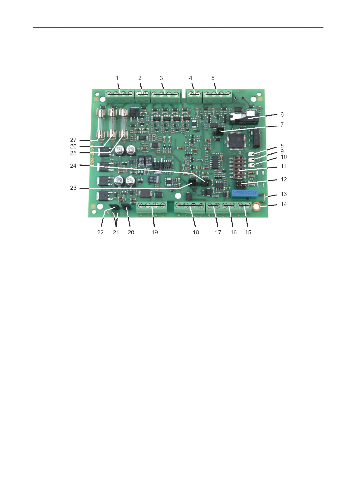
2.6.1 MB-Secure Siren Module (item no.013920)
1 = Connection Sirens 1 and 2; acoustic signaling device 048700/048720 (PCL)
or 160455.10/160456.10* (intrusion/hold-up alarm)
2 = Flash lamp connection
3 = Outputs A1 to A4 12 V/50 mA
4 = 0 V connections for outputs A1 to A4
5 = Analog inputs 1 and 2, clearable
6 = Cover contact
7 = Programming jumper P4; selection 048700/048720 or 160455.10/160456.10*
8 = LED 1 (to be used in-house only)
9 = LED 2 (to be used in-house only)
10 = LED 3 (to be used in-house only)
11 = BUS address programming switch
12 = To be used in-house only
13 = Grounding bridges (see chapter Grounding)
14 = Contact area for ground connection (PE) to the mounting bottom
15 = BUS wire shields. Important: Direct connection to the contact area for ground connection
16 = Connection for potential separation module 026595.10
17 = BUS supply voltage, additional connection in case of increased number of wires
18 = BUS-2/RS-485 connection (RS-485 in preparation) (Exclusive wired connection: data bus connection)
19 = Supply voltage for module
20 = Drill protection connection. If not used, terminate via jumper
21 = Connection points for tear-off protection
22 = Programming jumper tear-off protection; if tear-off protection is used, jumper not set
23 = Programming jumper P7; BUS interface operating mode BUS-2/RS-485 (RS-485 in preparation)
24 = Programming jumper P2/P3; terminating resistors RS-485 (RS-485 in preparation)
25 = fine-wire fuse 5 x 20 mm Si1 Flash lamp, 1 AF
26 = fine-wire fuse 5 x 20 mm Si2 Siren 1, 0.5 AF
27 = fine-wire fuse 5 x 20 mm Si3 Siren 2, 0.5 AF
 Loading...


