968XTP Maximum Security Switch - Installation Instructions
- 1 - PRELIMINARY DRAFT 11/4/09
BALANCED MAGNETIC
HIGH SECURITY SWITCH
Z
Y
X
(inward
swinging)
(outward
swinging)
Approach Distance
inches / mm
Removal Distance
inches / mm
0.17 / 4.3 0.42 / 10.6
0.53 / 13.5 0.72 / 18.2
0.23 / 5.7 0.54 / 13.7
Inswinging Door Instructions
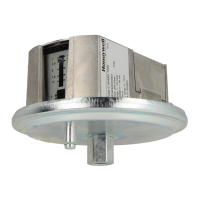
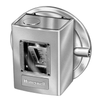
Honeywell’s 968XTP Maxiumum Security Magnetic Switch is intended to monitor the open or closed position of doors, windows, machinery
safety barriers or other movable assemblies in critical environments where an attempt to defeat the switch is a concern. The switch includes
numerous design features that make it highly defeat-resistant, reduce false alarms and provide for easy and accurate installation.
The performance of the 968XTP is unaffected by the type of surface on which it is mounted (steel or wood). The 968XTP features an
attack-resistant steel jacketed cable.
Step 1 - Install the Tamper Plate
• Line up the edge of the tamper plate with the edge of the door
frame, 1/2” (12.7 mm) [minimum] from the side edge. The
arrows on the tamper plate must be pointing toward the door.
• Mark the six hole centers for drilling pilot mounting holes.
• Drill two #6 (3.5 mm) pilot holes where shown.
• Drill four #8 (4.1 mm) pilot holes where shown.
• Mount the tamper plate in place using two #6 (3.5 mm) screws
[provided].
DOOR
Door
Frame
#6
3.5 mm( )
Screw
1/2”
(12.7 mm)
Open
#8
(4.1 mm)
Screw
#8
(4.1 mm)
Screw
Step 2 - Install the Switch
• Install the switch assembly to the tamper plate with four
#8 (4.1 mm) screws [provided]. Make sure that the arrow is
pointing toward the door.
Step 3 - Install the Magnet
• Align the edges of the magnet assembly to the edges of the switch assembly.
• Position the magnet assembly so the arrow faces the arrow of the switch assembly.
• Important: Gap distance must be 7/16 ±1/16” (11.1 mm ±1.6 mm).
• Mark the mounting holes, drill pilot holes for #8 (4.1 mm) screws [provided].
• Use the magnet spacer plates to align the front surface of the magnet to match the front surface of the switch.
• Verify that the arrow on the magnet assembly is facing the arrow on the switch assembly.
• Install the necessary spacer plates and magnet assembly on the door with two #8 (4.1 mm) screws [provided].
• See Supplemental Information for wiring instructions.
Align edges
7/16”
(11.1 mm)
Gap
Switch Assembly
Magnet Assembly
SEPARATE FOR USE
WITH MAGNET ONLY
TAMPER
SCREW
Align edges
Adjust height
with spacers