K5299V4 2/10 Rev. B
ADEMCO 5869
Holdup Switch/Transmitter
INSTALLATION AND SETUP GUIDE
GENERAL INFORMATION
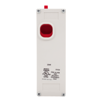
The ADEMCO 5869 Holdup Switch/Transmitter is a finger-
operated RF transmitting device used for activating a
holdup signal at the security system control, and/or any
other security application. The 5869 is typically mounted
under a counter or money draw for inconspicuous operation.
When the transmitter is activated, it sends an RF signal to
the control panel, which then sends a burglary alarm to the
central station.
Once the 5869 trigger (Figure 1) is activated, the supplied
reset key K4563 must be used to reset the device. The 5869
also contains tamper switches that are activated either
when the cover is removed, or when the unit is forcibly
removed from its installation location.
The 5869 has a permanent serial number assigned during
manufacture used for enrolling the 5869 with the security
system control panel. To enroll the 5869, refer to the
respective Security System Control Panel Installation and
Setup Guide.
For certified UL installations, the 5869 must be used
with the 5881ENHC tamper-protected wireless
receiver, mounted inside its plastic enclosure and
outside the alarm panel enclosure.
PROGRAMMING
The 5869 Holdup Switch/Transmitter should be
programmed as a 24-hour silent zone type. Refer to the
Security System Control Panel Installation and Setup
Guide for programming instructions.
NOTES:
• During programming of the control panel, the 5869
Holdup Switch/Transmitter should be treated as "RF"
(i.e., supervised RF) Type.
• The 5869 is one closed input loop zone (loop 1).
MOUNTING
Mount the 5869 under a counter or money drawer for easy
access by the cashier. Refer to the figure and steps that
follow for typical mounting installation.
Before mounting the 5869 permanently, perform Go/No Go
tests to verify adequate transmitter signal strength at desired
mounting location (refer to the Security System Control
Panel Installation and Setup Guide).
1. Install the battery into the battery holder observing
correct polarity as shown in Figure 2.
2. Position the case to the desired location and install one
No. 6 x ¾ screw (supplied) at the breakaway tamper
release hole as shown in Figure 3.
3. Secure the cover to the case with the two screws (No 6 x
1/2) as shown in Figure 3.
IMPORTANT: To prevent damage to the case, do not
over tighten the cover screws.
4. Secure the case with the cover to its mounting location
using the two screws (No. 6 x 2) supplied as shown in
Figure 3.
5869-002-V1
MOUNTING
HOLE
(TYP.)
RESET
KEY
COVER
TAMPER
SWITCH
BREAKAWAY
TAMPER
SCREW
No. 6X3/4
COVER
3V
LITHIUM
BATTERY
COVER
ATTACH
HOLE
COVER
ATTACH
HOLE
MOUNTING
SCREW (2)
No. 6X2
TRIGGER
+
+
ANTENNA
COVER
SCREW (2)
No. 6X1/2
COVER
SCREW (2)
No. 6X1/2
Figure 1. 5869 Holdup Switch/Transmitter Details
5869-006-V0
3V LITHIUM
BATTERY
+
TRIGGER
-
NOTE:
THE NEGATIVE (
-
)
SIDE OF THE BATTERY
MUST FACE THE TRIGGER
ANTENNA
Figure 2. 5869 Battery Installation