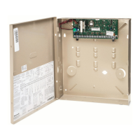
Signal Strength and Status LED Meanings
Color Label Indication
Red RSSI on = signal strength (RSSI) display
off = status display
Yel (2) mode off = module operating in ECPmode
Green Web web connection status
ON = connected to web
OFF = no web connection
Green GPRS GPRS service availability
ON = GPRS service available
FLASH = GPRS in use
OFF = no GPRS service (messages sent via SMS)
Green GSM network carrier registration status
ON = registered with network carrier, no second site available
FLASH = registered with network carrier and second site available, excellent RSSI
BLINK = registered with network carrier and second site available, acceptable RSSI
SLOW BLINK = registered with network carrier and second site available, low RSSI
OFF = control not registered with network carrier
V21iP-018-V2
GRN
LEDs
OFF
SLOW
BLINK
BLINK FLASH
ON
WEB NO WEB
CONNECTION
CONNECTED
TO WEB
IP/GSM SWITCHES
TEST STATUS
LED
INDICATOR
GND Z5Z4GNDZ3Z2GNDZ1+YELGRNAUXAC AC BELL GND GNDRINGTIPRINGTIPZ8GND Z6 Z7
1
2
3
7
8
11
12
17
20
21 22 23 24 25
18
19
16
15
14
13
10
9
6
4
5
VISTA-GSM4G MODULE
Z1-
RJ45
CONNECTOR
GRN
GRN
YEL
STATUS
MESSAGE
FAULT
GRN
YEL
RED
IP (WEB)
NETWORK
LEDs
IP/GSM STATUS LEDs
MAC ID LABEL
VISTA-21iP CONTROL BOARD
GPRS GPRS IN
USE
NO GPRS
SERVICE
GPRS SERVICE
AVAILABLE
GSM REGISTERED
EXCELLENT
RSSI
REGISTERED
LOW
RSSI
REGISTERED
ACCEPTABLE
RSSI
MODULE NOT
REGISTERED
REGISTERED
NO 2nd SITE
AVAILABLE
IF NO GPRS, MESSAGE SENT VIA SMS
REGISTERED w/ NETWORK CARRIER AND 2nd SITE AVAILABLE
STATUS LED INDICATIONS
†††
†
††
††
ETHERNET LINK/ACTIVITY (ON=YES; OFF=NO)
LINK SPEED (ON=100 MB/S; OFF=10 MB/S)
NETWORK COLLISION (BLINK=DETECTED; OFF= NORMAL)
ON
OFF
RED
YEL
YEL
GRN
GRN
GRN
MINIMUM
LIT
ON
INTERNAL/EXTERNAL
IP/GSM
POWER JUMPER
Signal Strength and Status LED locations – Status LED Functions Table
Inadequate Signal
Strength;
Using Stand-Alone
Communication
Device
If sufficient signal strength cannot be achieved, take one of the following actions:
1. Try relocating the cabinet to an area with better reception.
2. If moving the cabinet cannot achieve sufficient signal strength, an external, stand-alone
communication device (ex. GSMV4G) can be used. Follow these steps:
a. Power down the control.
b. Remove the Internet cable from the RJ45 connector
(if connected) and disable the Internal IP/GSM
portion of the control board by moving the
Internal/External IP/GSM Jumper to the OFF pair
of pins.
c. Connect the communication device to the control’s
ECP terminals and complete all other
communication device wiring as required.
JUMPER IN OFF POSITION
V21iP-012-V0
RJ-45
CONNECTOR
d. Power up the control and the communication device.
e. Refer to ∗29 Menu mode, Enable INT IP/GSM prompt, for programming information.
f. Refer to the Installation and Setup Guide included with the communication device for the
registration procedure.
Programming Overview
2-19
 Loading...