AQ250 SERIES HYDRONIC CONTROL PANELS
68-0306—05 10
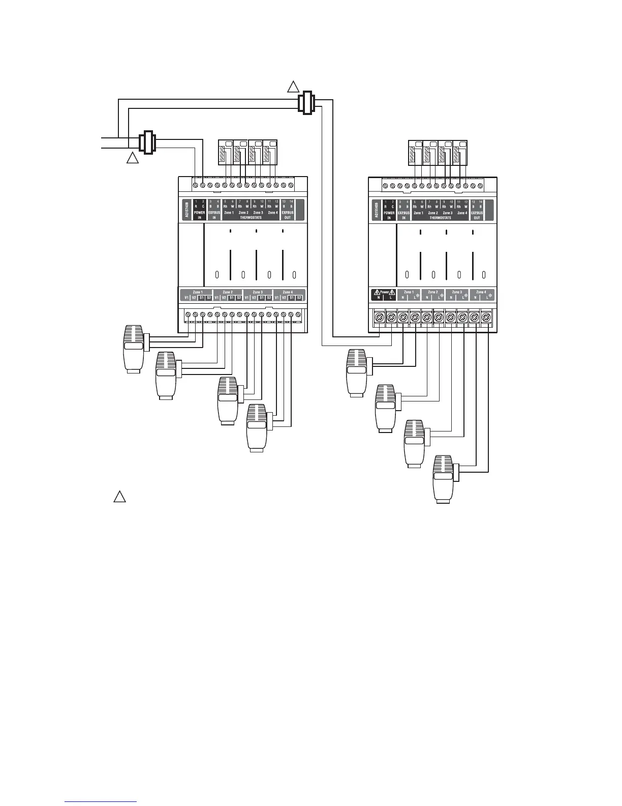
Fig. 13. Wiring of additional low voltage VA capacity.
Step 5 – Line Voltage System Outputs
See Fig. 14 and Fig. 15 on page 11 for wiring diagrams for the
line voltage outputs.
NOTE: It is not necessary to connect the boiler equipment’s
“T-T” terminals to the low voltage BOILER dry
contacts (Terminals 11-12) of the AQ250 when using
a Triple Aquastat on the boiler. See Fig. 15 on
page 11.
Follow these steps to wire the devices to the AQ250 Control
Module.
“1. Boiler Pump” on page 12
“2. DHW Aquastat Device” on page 12
“3. Line Voltage Rated Aux Output (optional)” on page 12
THERMOSTATS
ZONE 1 ZONE 2 ZONE 3
ZONE 4
M29038A
THERMOSTATS
ZONE 1 ZONE 2 ZONE 3
ZONE 4
Zone 1
Zone 2
Zone 3
Zone 4
USING AN AQ15740B
VALVE ZONING MODULE
POWER SUPPLY. PROVIDE DISCONNECT MEANS AND OVERLOAD PROTECTION AS REQUIRED.
1
Zone 1
Zone 2
Zone 3
Zone 4
1
2
3
1
2
3
1
2
3
1
2
3
1
2
3
1
2
3
1
2
3
1
2
3
24 VAC
100 VA
TRANSFORMER
115 VAC
115 VAC
24 VAC
100 VA
TRANSFORMER
1
1
USING AN AQ15540B
PUMP ZONING MODULE

 Loading...