Do you have a question about the Honeywell BendixKing KN 64 and is the answer not in the manual?
Overview of the manual's scope and purpose for KN 62/62A/64 DME.
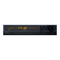
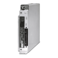
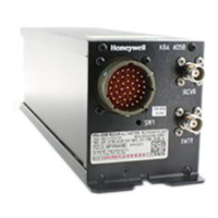
Detailed physical and functional overview of the KN 62/62A/64 DME unit.
Explains internal and external methods for channeling DME frequencies, including code types.
Lists critical frequencies that indicate mechanical resonance of the unit under test.
Information on the availability and part number for the KN 62 DME model.
Details on the available versions and part numbers for the KN 62A DME model.
Information on the available versions and part numbers for the KN 64 DME model.
Lists the contents of the installation kit for the KN 62/62A/64, including part numbers.
Provides general information related to the installation and wiring of the KN 62/62A/64 DME.
Instructions for safely unpacking and inspecting the DME unit for shipping damage.
Discusses the importance of proper avionics stack cooling for unit reliability.
Step-by-step instructions for physically installing the KN 62/62A/64 unit into an aircraft.
Detailed steps for assembling the Molex connector terminals and inserting them into the housing.
General guidelines for positioning and mounting the DME antenna on the aircraft.
Specific installation procedures for the KA 60/61 antenna, including drilling and mounting.
General operational recommendations and overview of the KN 62/62A/64 front panel controls and display functions.
| Weight | 2.5 lbs (1.13 kg) |
|---|---|
| Power Supply | 14/28 VDC |
| Channels | 200 |
| Display | LED |
| Operating Temperature | -20°C to +55°C |
| Mounting | Panel Mount |
| Type | DME |
| Frequency Range | 960 to 1215 MHz |
| Operating Voltage | 11 to 33 VDC |
| Range | 200 NM |
| Accuracy | ±0.1 nautical miles |
| Compliance | TSO-C66c |


