GB-5
GB
– For installation and operation, note the applicable
national regulations and the directives of the gas
supply company. For Germany, the valid DVGW
Code of Practice G600 (DVGW-TRGI) applies.
– Work on meters and the installation of meters
which are marked with and are installed in
potentially explosive atmospheres may only be
carried out by persons with appropriate qualifi-
cations.
– The gas meter marked with must be in-
cluded in the equipotential bond when being
installed in a potentially explosive atmosphere,
e.g. by connecting it to a grounded pipeline.
Installation must be carried out in accordance
with EN60079-14.
– The gas meter marked with must be pro-
tected from falling parts.
– Avoid subjecting the unit to mechanical stress
and prevent damage. Gas meters must be in-
stalled without any mechanical stress, preferably
only by suspending them on the connectors.
When using additional clamps, it must be en-
sured that no lateral forces act on the gas meter.
These can be avoided by using flexible or supple
connection lines, for instance.
▷ If the calibration seal has been damaged or re-
moved, the gas meter is no longer approved for
measurements which are subject to statutory
testing.
▷ If the gas meter is stored or installed outdoors,
protect the site against rain. Condensing humid-
ity is permitted.
▷ Meters which are marked with H3 are suitable
for installation outdoors without additional pro-
tection.
Remove protective caps.
▷
Installation in the vertical position: connectors
must be pointing upwards.
▷ Note direction of flow (arrow).
▷ The gas meter must not be in contact with ma-
sonry or other parts.
▷ Ensure that there is sufficient installation space.
▷ Ensure unobstructed view of the index.
▷
The seal faces on the screw unions must be
clean and damage-free.
▷ Ensure that the seal is correctly seated.
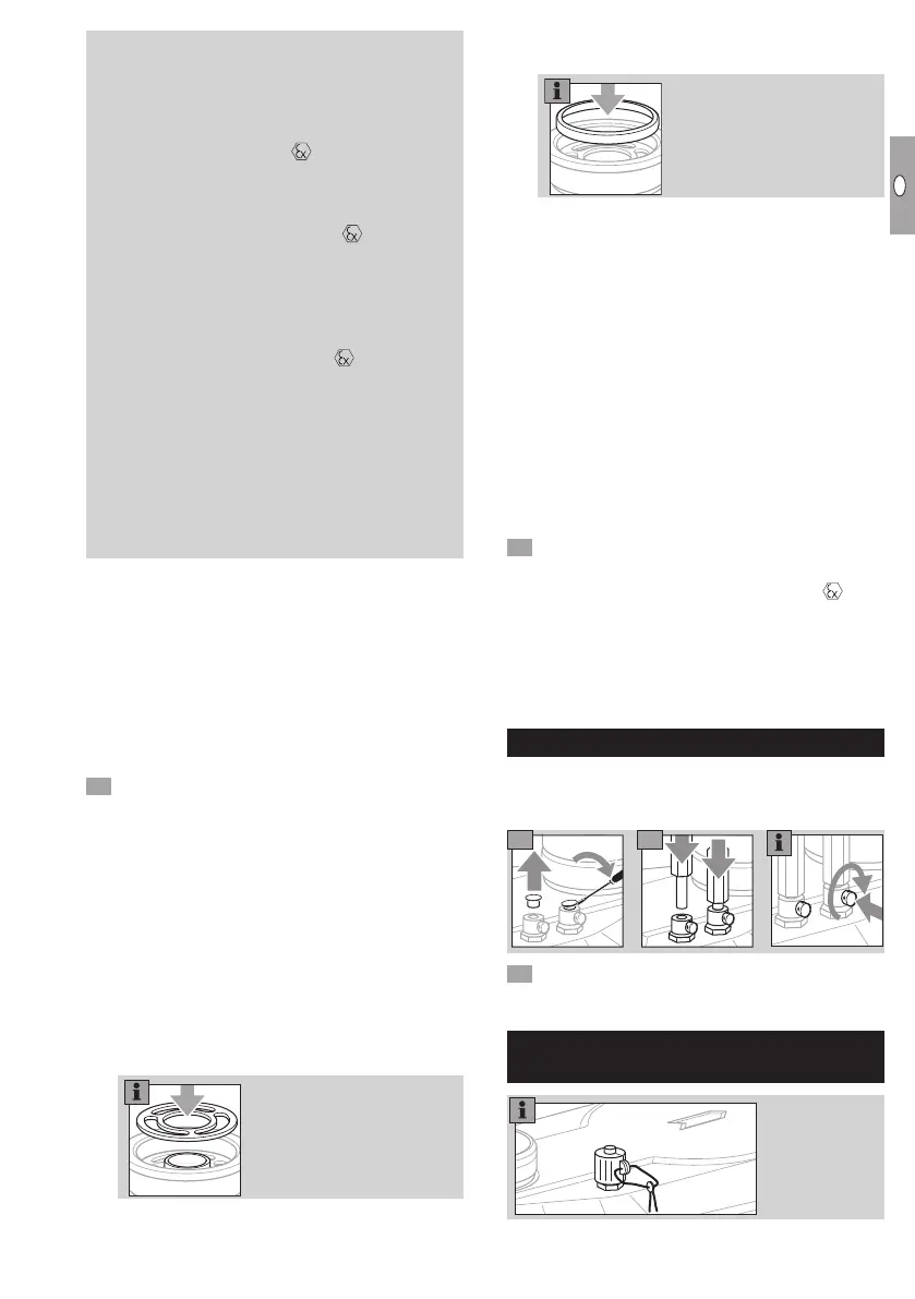
Co-axial meters:
▷ The seal must be centred over the internal dia-
meter.
▷
When using an elastomer seal, always use a
pressure ring (shape A).
▷
Note the installation position of the pressure ring.
The inner beaded edge must point upwards.
▷ Replace damaged pressure rings when replac-
ing the meter.
Co-axial and two-pipe meters:
▷ For the compression of seals and the resulting
tightening torques for the screw unions, the seal
manufacturers’ specifications must be observed.
Tightening torques for the recommended flat
seals in conjunction with screw connectors
pursuant to DIN 3376-1 and 3376-2, see
www.docuthek.com → Elster-Instromet → Prod-
ucts → Gas measuring devices → Diaphragm
meters → Ergänzung für Betriebsanleitung BK,
Verschraubungen und Anzugsmomente für BK-
G1,6 bis BK-G25 (Supplement to BK operating
instructions, Screw unions and tightening tor-
ques forBK-G1.6 toBK-G25)(D).
Install the gas meter free of mechanical stress.
▷
If a pulse transmitter IN-Z6x is used for pulse
tapping on the gas meter marked with – see
Data sheet for pulse transmitter IN-Z6x (D,GB)→
www.docuthek.com→ Elster-Instromet→ Prod-
ucts→ Gas measuring devices→ Diaphragm
meters→ Pulse transmitterIN-Z61 and the
standard EN60079-14 (Explosive atmospheres).
Temperature test point
▷
Temperature sensors can be inserted into the
thermowells for measuring the gas temperature
in the meter housing.
Secure each of the temperature sensors using
the capstan screw provided.
Pressure test point on housing
(optional)
 Loading...