GB-6
GB
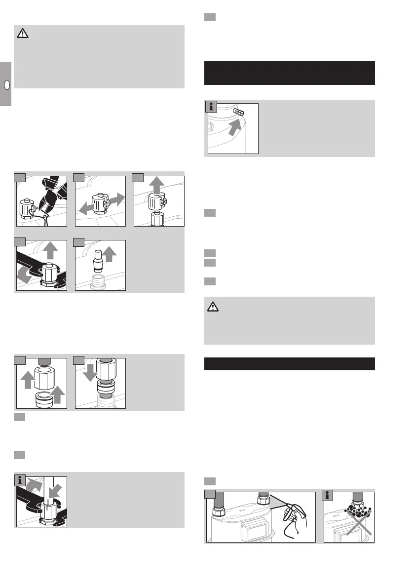
Connecting the piping
WARNING
In order to ensure that the gas meter is tight:
– The pressure test nipple must not be twisted,
bent, or otherwise manipulated.
– When installing, always secure the pressure test
nipple using a suitable spanner.
▷
Functional safety and reliability are ensured only if
the material combination of the screw connector
and the pressure line are inter-matched.
▷
Only use the olive and the attached union nut
supplied. The olive is secured to the sealing
sleeve.
▷
When re-ordering, use original Parker EO pro-
gressive ring fittings PSR/DPR.
1
2
3
4
5
▷
Use corrosion-resistant, seamless precision steel
tube pursuant to DINEN10305-4 (external di-
ameter 6mm, material E235= 1.0308). For other
materials, use a suitable adapter and note the
Parker/EO recommendations.
▷ Install pipes free of mechanical stress.
6
7
8 Screw on the union nut by hand as far as it will
go.
▷
At the same time, press the end of the pipe firmly
against the stop.
9 Mark the position of the union nut and tighten
with about 1½ turns.
▷
When reinstalling, the union nut will be turned to
the original position and then further tightened
through approx. 30°.
0 Once the installation and tightness test are com-
plete, see page6 (Tightness test), protect the
pressure test point against external access with
the sealing sleeve and the seal.
Pressure test point on outlet
connector (optional)
BS4161-compliant pressure test nipple
▷
Use a 10 mm spanner to release/tighten the
test point screw.
▷
The test nipple is secured to prevent it turning
with the screw.
Opening the test nipple
Remove the screw from the test nipple com-
pletely.
▷ The gas connection is open.
Closing the test nipple
Insert the screw by hand as far as possible.
Tighten the screw with a torque of 3Nm +
0.5Nm.
Check for tightness, see page 6 (Tightness
test).
WARNING
If the test nipple has unexpectedly come loose,
the gas meter must be regarded as damaged and
must be replaced.
Tightness test
▷
Check the pipework for leaks prior to installa-
tion of the gas meter, in case the pipework is
tested with a greater test pressure than the max.
allowable operating pressurep
max
for the gas
meter. Otherwise, the installed gas meter may
be damaged.
▷ If a valve is integrated in the diaphragm gas me-
terBK, see page 3 (Diaphragm gas meters
with integrated valve), this must be opened for
the tightness test.
▷ Ensure the customer’s consumers are closed.
Apply the test pressure slowly to the gas meter.
▷ If a pressure measuring line has been retrofitted
to the diaphragm gas meter, check this connec-
tion for tightness.
 Loading...