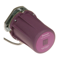
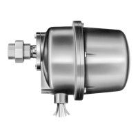
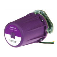
C7061A,F DYNAMIC SELF-CHECK ULTRAVIOLET FLAME DETECTOR
5 65-0223—07
In most installations, the detector needs to respond to the pilot
flame alone, then the pilot and main burner flame together, and
finally the main burner flame alone. The detector must meet all
sighting requirements that apply:
• Pilot flame alone—the smallest pilot flame that can be
detected must be capable of reliably igniting the main
burner.
• Pilot and main burner flame together—the detector must
sight the junction of both flames.
• Main burner flame alone—the detector must sight the most
stable part of the flame for all firing rates.
Parallel Flame Detectors
Shifting flame patterns, commonly encountered on burners
with high turndown ratios, can require two parallel detectors to
prove the flame at the highest and lowest firing rates and for
modulation in between. In this case, one detector supervises
the pilot (interrupted) and both detectors supervise the main
burner flame. During the main burner run period, either
detector is capable of maintaining system operation. A
maximum of two C7061 Detectors can be connected in
parallel.
In addition to assuring more reliable flame detection, parallel
detectors facilitate maintenance during burner operation. Each
detector can be removed, in turn, without shutting down the
supervised burner. However, a flame simulating failure
occurring in the flame signal amplifier or in either detector will
cause a shutdown.
Screening Effects
Smoke, oil mist, dirt and dust are masking agents that
attenuate the ultraviolet radiation that the flame emits. If they
absorb too much radiation, the amount of ultraviolet radiation
reaching the detector is reduced. The flame signal can then
become too low to hold in the flame relay, resulting in burner
shutdown.
The problem can be eliminated by diluting the contaminants. A
strong flow of air through the sight pipe will clear a viewing path
through the attenuating material. Refer to the Sight Pipe
Ventilation section.
It is also desirable to sight the detector at an area containing
fewer masking agents such as near the burner nozzle or near
the entrance of the combustion air. Increasing the viewing area
of the detector by shortening the sight pipe or by increasing the
diameter of the sight pipe also reduces the attenuating effects
of masking agents.
Multiburner Requirements
(Flame Discrimination)
In addition to meeting the requirements for a single burner, a
multiburner installation requires discrimination between flames.
Flame discrimination can be defined as locating all flame
detectors so that each detector responds only to the flame of
the burner it is supervising.
In multiple burner systems, not every detector can be
positioned so its line-of-sight does not intercept flames from
other burners. For example, this situation occurs in front-fired
boiler-furnaces having more than one row of burners, or in
multilevel opposed-fired furnaces where the burners face each
other.
When planning such an installation, locate each flame detector
so that it has the best possible view of the first 30 percent
closest to the burner nozzle (the flame root) it is supervising,
and the worst possible view of all other flames.
Fig. 4 illustrates a critical detector application problem that
requires flame discrimination. Flame discrimination is
accomplished for Detector A by repositioning it until the flame
relay (in the flame safeguard control) does not respond to
Flame B. Note that Detector A is aimed at the first 30 percent
of Flame A where the ultraviolet radiation is most intense. It
sights the tip of Flame B, but it is not aimed at the first 30
percent of Flame B where UV is intense. Detector A is
repositioned to assure maximum response to Flame A while
rejecting Flame B. Similarly, Detector B is positioned to assure
maximum response to Flame B while rejecting Flame A.
If you reposition a detector and still cannot achieve flame
discrimination, try reducing the viewing area by increasing the
length or decreasing the diameter of the sight pipe, or adding
an orifice plate.
Fig. 4. Example of flame discrimination
problem (opposed fired burners).
Install the Sight Pipe (Fig. 5)
After you have determined the location and sighting angle,
select the sight pipe. A black iron pipe with a diameter of at
least 1-1/2 in. (38 mm) is recommended. Do not use stainless
steel or galvanized pipe because they reflect ultraviolet
radiation internally and complicate aiming the pipe.
Sight pipes with diameters 2 to 3 in. (51 to 76 mm) produce
better results for horizontal rotary burners, which require wide
viewing angles. A wide viewing angle can also be obtained by
using a short sight pipe.
DETECTOR A
FLAME A
FLAME B
DETECTOR B
M1957
 Loading...