EasyManua.ls Logo

Honeywell C7007A - User Manual

Honeywell C7007A
8 pages
To Next Page IconTo Next Page
Loading...
INSTALLATION INSTRUCTIONS
60-2024-06
SIL
3
Capable
C7007A, C7008A, C7009A Flame
Rod Holder & Flame Rod
Assemblies
The small size of these devices enable their application to
flame detection in installations where space is limited. The
holder and flame rod assemblies facilitate flame proving on
gas burners or gas-ignited oil burners which are controlled by
electronic flame safeguard systems.
The C7007A, C7008A, and C7009A may be used with
flame safeguard controls utilizing the rectification principle
of flame detection.
The C7007A is a small, sturdy holder for a 3/16 inch [4.8
mm] diameter flame rod (flame rod ordered separately).
The holder is externally threaded (1/2-14 NPT) for pipe
mounting.
A collet chuck and setscrew position a flame rod securely.
If additional support of the flame rod is required, the
C7007A extension assembly is internally threaded (1/8-27
NPT) to accept a 1/8 inch iron support pipe.
The C7008A is a miniature flame rod assembly with a
threaded (external 1/4-18 NPT) base, snap-on cover, and
flame rod.
The C7008A can be used without the cover and a
coverless model is available.
The C7008A is available with several lengths of flame rod.
One end of the flame rod is threaded for insertion into the
C7008A and the other end may be cut to an exact size.
The C7009A is a smaller diameter flame rod assembly with
an externally threaded (1/8-27 NPT) base and readily
accessible Rajah electrical connection.
The C7009A has a 12 inch (305mm) flame rod which one
end is threaded and the other capable of being cut to an
exact size.
IMPORTANT
The specifications given in this publication do not
include normal manufacturing tolerances. Therefore,
this unit may not match the listed specifications
exactly. Also, this product is tested and calibrated
under closely controlled conditions, and some minor
differences in performance can be expected if those
conditions are changed.
SPECIFICATIONS
Tradeline Models:
C7008A Flame Rod Assembly, straight pattern, with cover
(can be used with or without cover).
FLAME RODS
C7008A1174, 12 inch [305 mm] Kanthal A1 C7008A1182, 24
inch [610 mm] Kanthal A1 see also, Accessories.
DIMENSIONS:
See Fig. 2.
ELECTRICAL CONNECTION:
Rajah male with companion connector.
MOUNTING:
Equipped with external 1/4-18 NPT threads.
STANDARD MODELS
C7007A Flame Rod Holder.
C7008A Flame Rod Assembly:
Miniature flame rod assembly.
C7009A Flame Rod Assembly: small diameter flame rod
assembly.
MOUNTING MEANS:
C7007A-external 1/2-14 NPT for pipe mounting.
C7008A-external 1/4-18 NPT for pipe mounting.
C7009A-external 1/8-27 NPT for pipe mounting.
FLAME ROD:
C7007A-Not furnished, refer to ACCESSORIES.
C7008A-Kanthal in 6, 12, 18, 24 inch [152, 305, 457, 610 mm]
lengths.
C7009A-Kanthal in 12 inch [305 mm] lengths.
Question and Answer IconNeed help?

Do you have a question about the Honeywell C7007A and is the answer not in the manual?

Honeywell C7007A Specifications

General IconGeneral
BrandHoneywell
ModelC7007A
CategorySecurity Sensors
LanguageEnglish

Summary

Installation Instructions

Specifications

Tradeline Models and Flame Rods

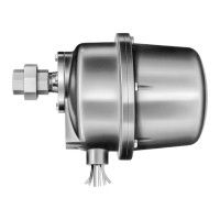
Details C7008A assembly and available flame rod lengths, materials, and specifications.

Dimensions and Electrical Connection

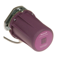
Provides physical dimensions and describes the Rajah male electrical connection type.

Mounting and Standard Models

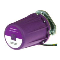
Specifies mounting thread sizes and identifies standard C7007A, C7008A, C7009A assemblies.

Key Features and Approvals

SIL 3 Capability

Details SIL 3 capability when integrated with specific Honeywell safety instrumented systems.

Product Approvals

Lists Underwriters Laboratories, CSA, and Factory Mutual certifications for the assemblies.

Available Accessories

Mentions optional ignition and detector cables for specific installation environments.

Installation and Mounting Guidance

Installation Warning

Cautionary note advising users to follow instructions to prevent damage or hazards.

Mounting Location and Position

Guidance on selecting optimal locations and angles for flame rod placement.

Flame Rod Positioning Examples

Illustrates correct and incorrect flame rod positions relative to pilot burners.

Installation Details and Wiring

Flame Rod Installation Procedure

Steps for positioning, securing, and permanently mounting the flame rod assembly.

Flame Grounding Requirements

Explains the necessity and methods for providing adequate electrical ground for flame detection.

Wiring Safety Caution

Warning to disconnect power before making wiring connections to prevent shock or damage.

Operation and Maintenance

Flame Rod Replacement Procedures

Step-by-step instructions for replacing flame rods in C7007A, C7008A, and C7009A models.

Oil Burner Usage Considerations

Notes on preventing oil or soot deposits on the flame rod insulator for reliable operation.

Flame Signal Measurement

Guidance on measuring flame signal current or voltage for performance verification.

Related product manuals