C7007A, C7008A, C7009A FLAME ROD HOLDER & FLAME ROD ASSEMBLIES
5 60-2024—06
Protect the leadwire from excessive radiant or reflected heat.
If any portion of the wire will be exposed to temperatures in
excess of 125° F [51.6° C], a heat-resistant wire should be
used (see Accessories). For wiring where temperatures do
not exceed 125° F [52° C], wire with thermoplastic insulation
may be used. If wire is enclosed in conduit, install a two foot
flexible connection to the head of the unit. This permits easy
removal of unit from combustion chamber.
FLAME ROD REPLACEMENT
To replace flame rod in the C7008A: remove the cover, pull off
the Rajah connector with the wiring, remove (unscrew) the
terminal nut and the lock washer at the base of flame rod
assembly to free the flame rod. Pull out the old flame rod and
insert the new rod. Then replace the lock washer, screw on
the terminal nut, push the wiring connector back on, and
replace the cover.
Procedure is the same for C7009A except that there is no
cover.
To replace flame rod in the C7007A: Remove the cover,
loosen the flame rod setscrew, pull the flame rod out, insert
the replacement rod, and tighten the setscrew. Replace the
cover.
A NOTE ON OIL BURNER USAGE
If the flame rod is used to prove a gas pilot on an oil
installation, oil or soot deposits must not be allowed to form on
flame rod insulator. Such deposits might form leakage
resistance paths, which in turn could cause nuisance
shutdowns of main burner.
Flame rod and porcelain insulators should be periodically
examined for oil or soot deposits. Such deposits should be
cleaned off before unit is put back in replace.
The performance of the C7007A Holder (with flame rod) and
C7008A, C7009A Flame Rod Assemblies can be determined
by measuring the flame signal (current/voltage) during pilot
burner operation.
Most existing Honeywell flame safeguard controls incorporate
a flame signal jack on the amplifier or the control itself. The
flame current measurement is made with a volt-ohm-meter
such as the Honeywell W136A Meter or a microammeter with
a zero to 25 microampere scale. A meter connector plug (part
no. 196146, provided with the W136A) is used to adapt the
W136A to the flame current jack on the flame safeguard
control. The W136A Meter probes are connected to the two
ends of the connector plug (red to red, black to black). The
plug end of the connector inserts directly into the flame current
jack of the flame safeguard control (see Fig. 11). If the flame
safeguard control does not have a meter jack, or if a meter
connector plug is not available, a meter can be wired in series
with the "F" lead of the flame detector circuit. During the
burner run cycle, the minimum acceptable flame current is two
microamperes.
The Honeywell BCS 7700 and 7800 SERIES controls provide
for a voltage flame signal measurement. A 20,000 ohm/volt
meter with a zero to 5 or 10 Vdc scale is recommended for the
BCS 7700 measurement and a one megohm/volt meter is
suggested for the 7800 SERIES controls. The flame signal
measurement is made by inserting the positive (red) meter
probe into the control positive (+) jack and the negative (black)
probe into the negative (-) jack of the BCS 7700 or the (-Com)
jack of the 7800 SERIES control (see Figs. 12, 13). With the
system in operation, the minimum acceptable flame signal
voltage is 1.25 Vdc for the 7800 SERIES controls and 2.2 Vdc
for the BCS 7700 control.
A low flame signal reading indicates the photocell is not
receiving sufficient visible flame radiation. Low flame currents
can be the result of an improperly positioned sight pipe,
restricted field of view, contaminated protective window or
focusing lens, or a defective photocell. Flame signals of 4 to 6
microamperes for existing controls and up to 5 Vdc for the
BCS 7700 and 7800 SERIES controls can be expected on
good applications/installations.
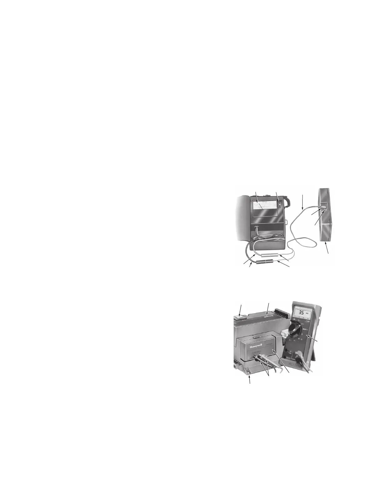
Fig. 10. Measuring microamp flame signal.
Fig. 11. Measuring BCS 7700 controls flame signal
voltage.
W136A VOLT-
OHMMETER
W136A SELECTOR
SWITCH
196146 METER
CONNECTOR
PLUG
PLUG
FLAME SIGNAL
METER JACK
PLUG-IN FLAME
SIGNAL AMPLIFIER
RED CONNECTOR
BLACK CONNECTORBLACK (-) METER LEAD
RED (+)
METER
LEAD
M6532A
RESET
BUTTON
B
PROGRAM
MODULE
20,000
VOLT-
OHM METER
V
O
METER
PROBES
P
FLAME
AMPLIFIER
BCS 7700 CHASSIS MODULE FOOT MOUNT
M7860
 Loading...