C7110C1040 AND C7110C1080 WALL MODULES – PRODUCT DATA
3 EN0B-0775GE51 R0619
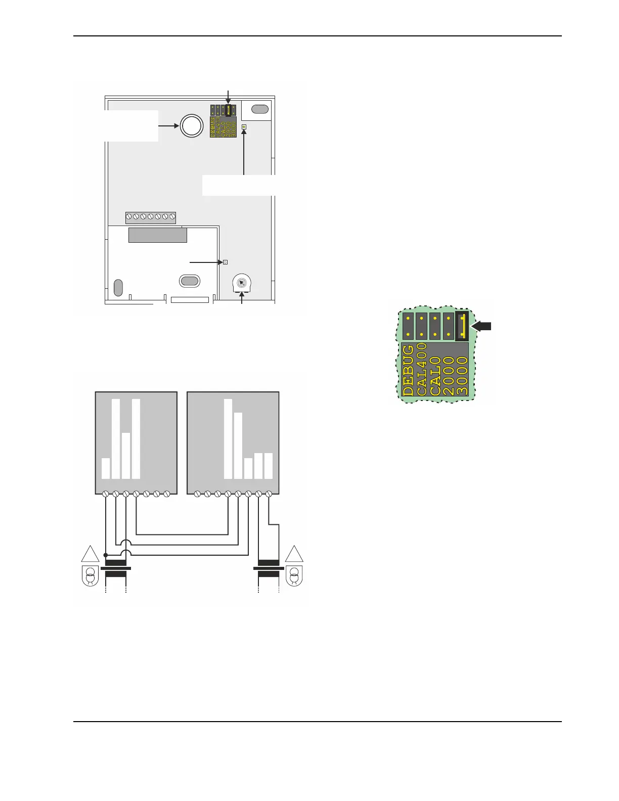
WIRING
1234
5
67
SERVICE LED
PRINTED CIRCUIT
BOARD
CONFIGURATION POTENTIOMETER
CONFIGURATION JUMPER
LED USED
FOR CALIBRATION
OCCUPANCY
BYPASS BUTTON
(C7110C1080, only)
SCREW TERMINALS
Fig. 3. PCB, main features
The screw terminals, located on the Printed Circuit Board
(see Fig. 3), are suitable for connecting 0.3 to 1.5 mm
2
(16…22 AWG) wiring. The assignments of terminals 1
through 7 for both models are depicted in Fig. 4.
12
3
45
6
7
######
C7110C1040 / 1080
CONTROLLER
COM
COM
TEMPERATURE INPUT
CO2 INPUT 0...10 V
PT1000 / NTC 20kOhm
! !
24 VAC
24 VAC
CO2 OUTPUT 0...10 V
24 VAC/DC
LINE
OLTAGE
LINE
OLTAGE
Fig. 4. Wiring C7110C1040 / 1080 to controller and
separate safety transformer
CONFIGURATION
The wall module can be configured using its configuration
jumper and/or its configuration potentiometer.
Configuration Jumper
The wall module's calibration modes can be selected and the
CO
2
measuring range extended by repositioning the con-
figuration jumper located on the Printed Circuit Board (see
Fig. 3).
IMPORTANT
Do not change the position of the configuration
jumper before first removing power.
In a normal environment, the unit is maintenance-free.
Accurate measurement is guaranteed by the built-in ABC self-
calibration feature (see below).
Setting Range to 2000 ppm or 3000 ppm
"2000" ppm
When the configuration jumper is set to the factory default
position of "2000" ppm (see Fig. 8) – or to any other position
except "3000" ppm (see Fig. 5) – the CO
2
measuring range is
400…2000 ppm.
"3000" ppm
Fig. 5. Jumper set to 3000 ppm
When the configuration jumper is set to position "3000" ppm
(see Fig. 5), the CO
2
measuring range will be expanded to
400…3000 ppm.
Quick Calibration Methods
In the event that one cannot wait for ABC to gradually correct
measurement errors, it is possible to make use of either one
of the following two quick calibration methods:
▪ Zero Calibration or
▪ Fast Background Calibration (recommended method).
These quick calibration methods typically take about 2
minutes.
IMPORTANT
Do not change the position of the configuration
jumper before first removing power.
After initiating the desired calibration process by removing
power and then repositioning the jumper, restore power and
then wait until the calibration process has been completed
(see "Behavior of Service LED during Quick Calibration")
before again removing power, returning the jumper to the
desired range setting (i.e., "2000" or "3000"), and finally
restoring power.
 Loading...