C7110C1040 AND C7110C1080 WALL MODULES – PRODUCT DATA
5 EN0B-0775GE51 R0619
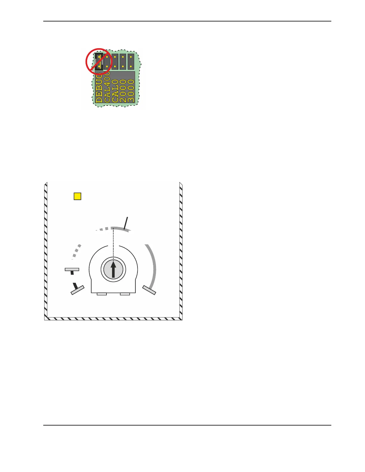
"DEBUG"
Fig. 10. Do not set jumper set to DEBUG!
DO NOT USE!
Configuration Potentiometer
The wall module features a configuration potentiometer
(accessible only after removing the top cover) which can be
used to configure the output of terminal 2 (CO
2
level) and
(when in the "Relay Output" mode) the "Threshold Level
(ppm)".
SERVICE LED
MAX.
OFF
SERVICE
LED IS LIT
SERVICE LED
FLASHES
MIN.
SERVICE
LED IS DARK
50% =
1000 ppm
ACTUAL CO2
CONCENTRATION
(EXAMPLE)
Fig. 11. Configuration potentiometer (e.g., set to 50% =
1000 ppm)
The CO
2
output can operate in two modes:
▪ To select the "Sensor Output" mode (analog), set the
configuration potentiometer to "OFF" (default setting) (see
Fig. 11). See also Fig. 12.
▪ To select the "Relay Output" mode (digital), set the con-
figuration potentiometer to between the "MIN." and "MAX."
markers (see Fig. 11). The hysteresis value is
permanently set to 100 ppm. See also Fig. 13.
 Loading...