C7110C1040 AND C7110C1080 WALL MODULES – PRODUCT DATA
EN0B-0775GE51 R0619 6
The "Sensor Output" Mode
In the "Sensor Output" mode (analog), the Service LED (see
Fig. 11) is always dark.
10 V
P
ERMINA
2
0 V
2 V
0
ppm
400
ppm
2000
(3000)
ppm
CO2 LEVEL
SERVICE LED IS
Fig. 12. Sensor output mode (analog)
In the "Sensor Output" mode (analog), terminal 2 delivers an
analog output of 0…10 V. You can then configure a
measuring range of either 400 to 2000 ppm or 400 to 3000
ppm, depending upon the position of the configuration jumper.
Due to ABC calibration to 400 ppm, given measured concen-
trations below 400 ppm, the output signal will gradually rise to
2 V.
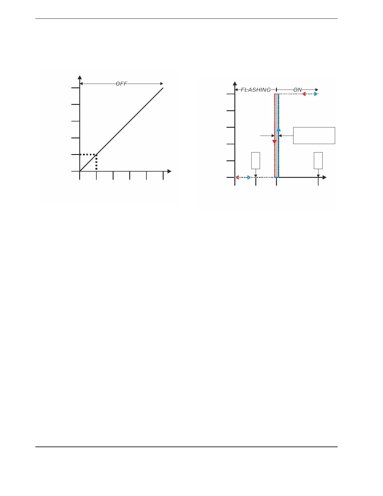
The "Relay Output" Mode
In the "Relay Output" mode (digital), the Service LED (see
Fig. 11) will either flash or be lit continuously, thus indicating
the actual Threshold Level setting.
10 V
500
ppm
1000
ppm
0 V
HYSTERESIS
(100 ppm)
CO2 LEVEL
2000
(3000)
ppm
MIN.
MAX.
SERVICE LED IS
P
ERMI
A
2
Fig. 13. Relay output mode (digital)
In the "Relay Output" mode (digital), terminal 2 delivers digital
output (of 0 / 10 V). You can then configure a "Threshold
Level (ppm)" of any value between MIN. = 500 and MAX. =
2000 (or 3000, if configuration jumper is in "3000 ppm") by
turning the configuration potentiometer (in the above
example, the Threshold Level has been set to 1000 ppm).
 Loading...