EN2R--9029 0101R2--NE
4
SPECIFICAT IONS
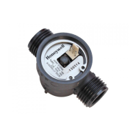
Model
C7195A water flow s ensor
Ambient temperature
--20 ... + 85 _C
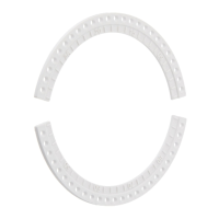
Dimensions
See fig. 11.
Fluid
Water for sanitary use
Permissib le fluid temperatur
0 ... 80 _C
Minimum operating flow rate
1.5 liter/minute or lower
Maximum operating flow rate
30 liter/minute
Mounting position
The shaft of the rotor shall be horizontal ¦ 5_. See fig. 5.
Provided the shaft of the rotor is horiz ontal, most
positions are acceptable, but the position as indicated in
fig. 6. is not recommended because water will remain in
the sensor when the installation is drained (frost risk).
All positions
Shaft axis
Shaft axis
5_
5_
5_
5_
Fig. 5. Mounting positions
Fig. 6. Not recommended mounting position
Measuring range
2.1 ... 30 liter/min
Nominal output frequency
f = Q x 7.0 (Q = flow rate in l/min; f = pulse signal in Hz) with
> 60 mm straight pipe on both sides.
Accuracy
¦ 10% of measurement over the measuring range.
Withstand pressure
When a water pressure of 17.5 bar is applied, no external
leakage shall be measured and no body damage shall occur.
Water connections
PF
1
/
2
” minimum 8 mm (4.4 threads)
Recommended tightening torque of inlet/outlet connections
2.5 ... 3.5 Nm
Pressure drop
0.15 bar or less at 10 l/min flow rate.
(Outlet pressure is at atmospheric pressure)
Endurance
Indicated value will shift < 5% under following conditions:
10000 hr at 10 l/min and 20 _C
7000 hr at 4 l/min and 45 _C
or
100,000 cycles ON/OFF at 10 l/min and 45 _C
 Loading...