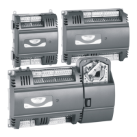
LYNX LON PROGRAMMABLE, VAV/UNITARY CONTROLLERS – PRODUCT DATA
EN0Z-0957GE51 R0615 10
Table 4. Description of wiring terminals (CLLYUL1012S,
CLLYUL4024S, CLLYVL0000AS, CLLYVL4022AS, and
CLLYVL4024NS)
TERMINAL
LABEL CONNECTION
CLLYUL4024S,
CLLYVL4024NS
CLLYVL4022AS
a
CLLYUL1012S CLLYVL0000AS
a
1 1 1 1 24 VAC 24 VAC power
2 2 2 2
24 VAC
COM
24 VAC power
3 3 3 3 EGND earth ground
4 4 4 4 20VDC 20 VDC
5 5 5 5 SBUS1 Sylk
6 6 6 6 SBUS2 Sylk
7 7 7 7 NET-1 LonWorks COM
8 8 8 8 NET-2 LonWorks COM
9 NA NA NA DO-3 digital output
b
10 NA NA NA COM common
b
11 NA NA NA DO-4 digital output
b
12 NA NA NA COM common
b
13 13 13 NA DO-1 digital output
b
14 14 14 NA DO-2 digital output
b
15 15 15 NA COM common
b
16 16 16 NA AO-1 analog output
c
17 17 17 NA COM common
c
18 18 NA NA AO-2 analog output
c
19 19 19 NA UI-1 univ. input
d
20 20 20 NA COM common
21 21 NA NA UI-2 univ. input
22 22 NA NA UI-3 univ. input
23 23 NA NA COM common
24 24 NA NA UI-4 univ. input
a
In the case of the CLLYVL0000AS, CLLYVL4022AS controllers, only,
terminals 9 and 11 (DO-3 and DO-4) are internally hardwired to the
actuator.
b
Digital outputs: Open circuit = FALSE, closed circuit = TRUE
c
Analog outputs may be configured as digital outputs and operate as
follows: FALSE (0%) -> 0 Vdc (0 mA), TRUE (100%) -> the max.
11 Vdc (22 mA)
d
UI-1* is a hybrid input. It can be configured either as a DI (fast digital
pulse meter) or as a UI.
IMPORTANT
If the controller is not connected to a good earth
ground, the controller's internal transient protection
circuitry is compromised and the function of protecting
the controller against noise and power line spikes
cannot be fulfilled. This could result in a damaged
circuit board and require replacement of the controller.
Refer to installation diagrams for specific wiring.
All controllers have terminal arrangements similar to the
examples shown in Fig. 13 and Fig. 14 as described in Table
3 and Table 4.
NEURON® Service Pin
When pressed, the NEURON® Service Pin pushbutton trans-
mits the Service Message to the network, regardless of the
controller's current operating mode (see Fig. 13 and Fig. 14).
CAUTION
Electrical Damage Hazard.
Can cause controller damage or failure.
Do not use any metal object to press the N
EURON®
Service Pin. Use, instead, a plastic rod or wooden
implement (such as a pencil with the lead broken off)
to press the pin. Using a metal object can damage the
controller's circuitry.
LonWorks Bus Convenience Jack
The LONWORKS® Bus connection is provided by plugging the
Serial L
ONTALK® Adapter (SLTA) connector into the
L
ONWORKS® Bus Jack (see Fig. 13 and Fig. 14).
12
3
4
5
67890
12
3
4
5
67890
2222222222
333333333
4
12
3
4
5
678
1
11111111121
2
3
4
5
6789009
CLLYVL6438NS
24 VAC
24 VAC COM
E GND
SHLD
SBUS1
SBUS2
NET-1
NET-2
DO-1
DO-2
COM
COM
COM
COM
DO-3
DO-4
DO-5
DO-6
DO-7
DO-8
AO-1
AO-2
AO-3
DI-1
DI-2
DI-3
DI-4
20VDC
UI-1
UI-2
UI-3
UI-4
UI-5
UI-6
COM
COM
COM
COM
COM
COM
TERMINALS 21-40
TERMINALS 9-20TERMINALS 1-8
LonWorks Bus Jack
(labelled SRV JCK)
Neuron Service Pin
(labelled SRV PIN)
HOST STATUS LED
Fig. 13. LED, LonWorks® Bus Jack, and Neuron® Service
Pin for the CLLYUL6438S, CLLYVL6436AS, and
CLLYVL6438NS (CLLYVL6438NS shown)
12
33
44
56789099
111111 222221
36790
4
5
1111112
11223344
55
667788901
11
2
DO-4
24 VAC
24 VAC COM
E GND
20VDC
SBUS1
SBUS2
NET-1
NET-2
DO-3
COM
COM
24 VAC
24 VAC COM
E GND
20VDC
SBUS1
SBUS2
NET-1
NET-2
DO-1
DO-2
AO-1
AO-2
UI-1*
UI-2
UI-3
UI-4
COM
COM
COM
COM
DO-1
COM
AO-1
COM
COM
UI-1
DO-2
TERMINALS 1-12 TERMINALS 1-8
TERMINALS 13-24 TERMINALS 13-20
NEURON SERVICE PIN
(LABELLED SRV PIN)
NEURON SERVICE PIN
(LABELLED SRV PIN)
LONWORKS BUS JACK
(LABELLED SRV JACK)
LONWORKS BUS JACK
(LABELLED SRV JACK)
CLLYVL4024NS CLLYUL1012S
Fig. 14. Terminal connections, Neuron® Service Pin, and
LonWorks® Bus Jack for the CLLYUL4024S,
CLLYVL4022AS, and CLLYVL4024NS (CLLYVL4024NS
shown left) and the CLLYUL1012S (right)
Wiring Applications (Examples)
Fig. 15 through Fig. 21 illustrate controller wiring for the
following configurations.
Typical controller wiring for VAV application using the
CLCM4T111 Wall Module and an LF20 Air Temperature
Sensor (see Fig. 15).
Typical controller wiring for VAV application with staged
reheat (see Fig. 16).
 Loading...


