EasyManua.ls Logo

Honeywell CENTRA LINE MERLIN NX Series User Manual

Honeywell CENTRA LINE MERLIN NX Series
43 pages
To Next Page IconTo Next Page
Page #1 background imageLoading...
Page #1 background image
® U.S. Registered Trademark
Copyright © 2022 Honeywell Inc. • All Rights Reserved
EN1Z-1076GE51 R0722
MERLIN NX
IP AND MS/TP VAV CONTROLLER
INSTALLATION
INSTRUCTIONS
General ......................................................................... 2
Trademark Information............................................... 2
Product Description ................................................... 2
Dimension.................................................................. 3
Network Security ......................................................... 3
General Safety Instructions........................................ 3
Specifications .............................................................. 4
Electrical .................................................................... 4
Operational Environment ........................................... 4
Sylk™ Supported Devices ......................................... 4
Hardware ................................................................... 4
Integrated Actuator......................................................... 4
Differential Pressure Sensor...................................... 4
BACnet Communications........................................... 5
Modbus Client............................................................ 5
Weight And Dimensions............................................. 5
Universal IO ............................................................... 5
Solid State Relay (SSR) ............................................ 5
Wireless Connectivity ................................................ 5
Standards and Compliances...................................... 5
HARDWARE OVERVIEW ............................................. 6
IP Variant ................................................................... 6
MS/TP Variant............................................................ 6
Controller Terminals ................................................... 7
Service Button ........................................................... 8
Mounting ...................................................................... 8
Before Mounting Actuator onto the Damper Shaft ..... 8
Mounting Actuator onto Damper Shaft....................... 9
Airflow Sensor Connection ...................................... 10
Differential Pressure Installation .............................. 11
Airflow Sensor Replacement ................................... 12
Power supply ............................................................. 13
General Information ................................................. 13
Power Wiring ........................................................... 13
Power Wiring Examples........................................... 14
Input / Output Wiring................................................. 15
Wiring Requirements ............................................... 15
Internal Wiring Examples......................................... 16
UIO Wiring Examples .............................................. 17
SSR (DO) Wiring Examples..................................... 18
20 VDC Auxiliary Wiring Examples.......................... 18
Networking Concepts................................................ 19
The RS485 Standard ............................................... 19
Network Topologies ................................................. 19
Daisy Chain ............................................................. 19
Spanning Tree Protocol (RSTP) .............................. 19
BACnet IP ................................................................... 20
DHCP IP Configuration............................................ 20
Static IP Configuration ............................................. 20
Connect to a IP network........................................... 20
Antenna ...................................................................... 20
Installing the Local Antenna ..................................... 20
Installing the Remote Antenna ................................. 20
Remote Antenna Placement .................................... 21
BACnet MS/TP VARIANT ........................................... 22
Termination Resistors .............................................. 22
RS-485 Bias Switches ............................................. 22
BACnet MSTP Wiring Example ............................... 22
BACnet MSTP Controller........................................... 23
Automatic MAC Addressing ..................................... 23
Manual configuration of the MAC Address............... 23
Setting the Device Instance Number ....................... 24
Connecting to BACnet MS/TP Buses ...................... 24
Modbus RTU............................................................... 25
Modbus Defaults ...................................................... 25
Wiring Topology ....................................................... 25
Modbus Master Specifications ................................. 25
Sylk Bus™ .................................................................. 26
Supported wall modules........................................... 26
Sylk Bus Wiring Examples ....................................... 26
Bluetooth Balancing.................................................. 27
Overview .................................................................. 27
Troubleshooting......................................................... 28
BACnet and Modbus LED Status............................. 28
Bluetooth LED Status............................................... 28
Controller LED Status .............................................. 28
Regulatory Information ............................................. 30
FCC Regulation ....................................................... 30
Canadian Regulatory Statement.............................. 30
Approvals and Certifications .................................... 31
Appendix .................................................................... 32
Sensor Input Accuracy ............................................. 32
Recognition of Sensor Failure of Sensor Inputs ...... 32
Sensor Characteristics.............................................. 32
PT1000 .................................................................... 33
PT3000 .................................................................... 36
NTC10K TYPE II...................................................... 36
NTC10K TYPE III..................................................... 37
PT100 ...................................................................... 37
JOHNSON A99 ........................................................ 38
NTC20K ................................................................... 38
10K3A1 .................................................................... 40
Nickel Class B DIN 43760 sensors .......................... 41
NI1000TK5000......................................................... 42
Related Technical Literature ..................................... 43

Table of Contents

Other manuals for Honeywell CENTRA LINE MERLIN NX Series

Question and Answer IconNeed help?

Do you have a question about the Honeywell CENTRA LINE MERLIN NX Series and is the answer not in the manual?

Honeywell CENTRA LINE MERLIN NX Series Specifications

General IconGeneral
Enclosure RatingIP20
Communication ProtocolBACnet
Power Supply24V DC
MemoryFlash memory
MountingDIN rail mount
Humidity Range5 to 95% RH, non-condensing

Summary

General

Trademark Information

Describes trademarks used in the document.

Product Description

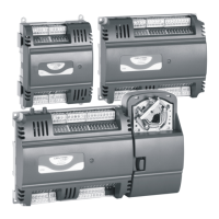
Describes the MERLIN NX family of controllers and their features.

Dimension

Network Security

Warns about cyber-attacks and network protection for controllers.

General Safety Instructions

Provides safety precautions for installation and handling.

Specifications

Electrical

Details electrical requirements and power consumption of the controller.

Hardware

Describes the CPU, memory, Ethernet, and Real Time Clock.

Operational Environment

Specifies storage, operation, humidity, protection, and pollution ratings.

Sylk™™ Supported Devices

Lists compatible wall modules and sensors for the Sylk™™ bus.

Differential Pressure Sensor

Details the range and accuracy of the DP sensor.

BACnet Communications

Details supported BACnet protocols and configurations.

Modbus Client

Describes Modbus client capabilities and specifications.

Weight And Dimensions

Provides physical dimensions and weight of the controller.

Universal IO

Details specifications for Universal Input/Output.

Solid State Relay (SSR)

Lists specifications for Solid State Relays.

Wireless Connectivity

Specifies wireless connectivity options like Bluetooth.

Standards and Compliances

Lists certifications and standards met by the controller.

HARDWARE OVERVIEW

IP Variant

Describes hardware features specific to the IP model.

MS/TP Variant

Describes hardware features specific to the MS/TP model.

Controller Terminals

Power Terminals

Details the terminals for power supply connections.

SSR Terminals

Describes the terminals for Solid State Relays.

Sylk Interface Terminals

Lists terminals for Sylk bus interface.

RS 485 Terminals

Details terminals for RS 485 communication.

UIO Terminals

Describes terminals for Universal Input/Output.

20 VDC Terminals

Details terminals for 20 VDC output.

BACnet MS/TP Terminals

Lists terminals for BACnet MS/TP.

Service Button

Pressing Service Button during Power-Up

Explains function when button is pressed during startup.

Pressing Service Button during Normal Operation

Explains function when button is pressed during normal operation.

Mounting

Before Mounting Actuator onto the Damper Shaft

Prepares for actuator installation on the damper.

Mounting Actuator onto Damper Shaft

Determine Damper Rotation

Guides on identifying damper opening direction and angle.

Tools Required

Lists necessary tools for actuator installation.

Setting the mechanical end limits

Actuator Mounting Procedures

Details steps for mounting actuator based on damper rotation.

Airflow Sensor Connection

Airflow Sensor Tubing

Specifies tubing requirements for airflow sensor connection.

Differential Pressure Installation

Zero Calibration

Notes the need for controller power for zero calibration.

Air Filter Recommendation

Recommends using an air filter for dusty environments.

Airflow Sensor Replacement

Removing the sensor cover

Describes how to remove the sensor cover.

Replacing the sensor

Details the process of replacing the airflow sensor.

POWER SUPPLY

General Information

Provides safety and general wiring advice for power supply.

Power Wiring

Details wiring compliance, wire gauge, and transformer requirements.

Power Wiring Examples

Single Controller Wiring

Shows wiring for one controller per transformer.

Multiple Controller Wiring

Illustrates wiring for multiple controllers per transformer.

Controller and Field Device Wiring

Depicts wiring for controllers and field devices.

INPUT / OUTPUT WIRING

Wiring Requirements

Specifies wire gauge and terminal connection methods.

Internal Wiring Examples

IP Model Internal Wiring

Diagram for internal wiring of the IP model.

MSTP Model Internal Wiring

Diagram for internal wiring of the MSTP model.

UIO Wiring Examples

Universal Input/Output Diagram

Shows connection examples for UIO terminals.

Voltage Output to Power External Relay

Illustrates wiring for voltage output to relay.

Analog Output Wiring

Details wiring for analog output.

SSR (DO) Wiring Examples

SSR Wiring with One Transformer

Shows SSR wiring with a single transformer.

SSR Wiring with Separate Transformer

Illustrates SSR wiring with a separate transformer.

20 VDC Auxiliary Wiring Examples

20 VDC Auxiliary Power Output

Diagram for 20 VDC auxiliary power wiring.

NETWORKING CONCEPTS

The RS485 Standard

Explains the RS485 standard and cabling requirements.

Network Topologies

Discusses recommended cable and distance for topologies.

Daisy Chain

Describes the daisy chain topology and its limitations.

Spanning Tree Protocol (RSTP)

Details RSTP for redundant ring connections.

BACNET IP

DHCP IP Configuration

Explains automatic IP address assignment via DHCP.

Static IP Configuration

Describes how to configure a static IP address.

Connect to a IP network

Details connecting the controller to an IP network.

Installing the Local Antenna

Guides on installing the controller's built-in antenna.

Remote Antenna Placement

Antenna Placement Guidelines

Provides advice on placing the remote antenna for optimal signal.

Wall Material Impact

Lists how wall materials affect Wi-Fi signal range.

BACNET MS/TP VARIANT

Termination Resistors

Explains the need and value for terminating resistors.

RS-485 Bias Switches

Describes the function of RS-485 bias switches.

BACnet MSTP Wiring Example

Shows a wiring diagram for MSTP communication.

BACNET MSTP CONTROLLER

Automatic MAC Addressing

Explains how MAC addresses are assigned automatically.

Manual configuration of the MAC Address

Details how to manually set the MAC address using DIP switches.

Setting the Device Instance Number

Device Instance Number Uniqueness

Explains the importance of unique device instance numbers.

Connecting to BACnet MS/TP Buses

BACnet MS/TP Bus Length

Refers to maximum bus length specifications.

BACnet MS/TP Limitations

Discusses physical and AutoMAC limitations.

MODBUS RTU

Modbus Defaults

Lists default Modbus RTU settings.

Wiring Topology

Describes allowed and prohibited Modbus wiring topologies.

Cables and Shielding

Provides guidance on Modbus cable selection and shielding.

RS485 Repeaters

Discusses the use and testing of RS485 repeaters.

Modbus Master Specifications

Details physical layer, rates, and address range for Modbus masters.

Modbus Compliance

Explains the controller's compliance level with the Modbus standard.

SYLK BUS TM

Supported Wall Modules

Lists compatible Sylk bus wall modules.

Sylk Bus Wiring Examples

Shows wiring examples for Sylk bus connections.

BLUETOOTH BALANCING

Overview

Introduces the Honeywell Connect Mobile app for VAV balancing.

TROUBLESHOOTING

BACnet and Modbus LED Status

Explains the meaning of BACnet/Modbus LEDs.

Bluetooth LED Status

Describes the status indicated by Bluetooth LEDs.

Controller LED Status

LED Status Interpretation

Details the meaning of controller status LEDs.

REGULATORY INFORMATION

FCC Regulation

States compliance with FCC rules for radio frequency energy.

Canadian Regulatory Statement

Compliance statement for Industry Canada.

CE Statement

Notes restrictions for WLAN function operating indoors.

EMF Statement

Advises on RF exposure separation distance.

Professional Installation Warning

Stresses need for professional installation and approved antennas.

Detachable Antennae Warning (IC)

Warning regarding approved antenna types for IC certification.

Approvals and Certifications

UL, CSA, BTL, CE, FCC Compliance

Lists various product approvals and certifications.

RoHS Conformity

States compliance with RoHS directives.

WEEE DIRECTIVE

Disposal instructions for product and packaging.

Article 33 Communication (REACH)

Information on substances in articles under REACH.

APPENDIX

Sensor Input Accuracy

Lists typical accuracies for NTC10K and NTC20K sensors.

Recognition of Sensor Failure

Explains how sensor failures are detected and thresholds.

Sensor Characteristics

Refers to resistance/temperature characteristics on following pages.

RELATED TECHNICAL LITERATURE

MERLIN NX IP Product Datasheet

Provides reference for the IP product datasheet.

MERLIN NX MSTP Product Datasheet

Provides reference for the MSTP product datasheet.

MERLIN NX IP and MSTP Mounting instructions

Reference for mounting instructions.

Related product manuals