MERLIN NX IP AND MST/TP VAV CONTROLLER - INSTALLATION INSTRUCTIONS
EN1Z-1076GE51 R0722 10
The actuator mounts directly onto the VAV box damper
shaft and has up to 44 in-lb. (5 Nm) torque, 90-degree
stroke, and 108 second timing at 50 Hz and 90 second
timing at 60 Hz.
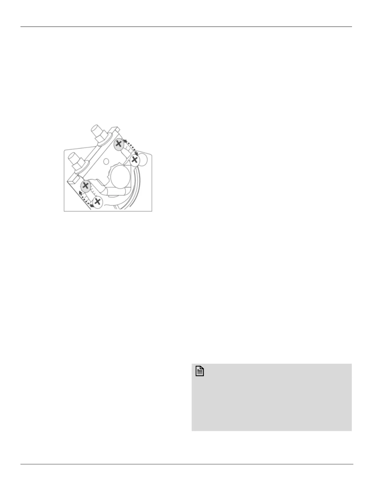
The actuator is shipped with two mechanical end limit set
screws to control the amount of rotation from 12° to 95°.
These set screws must be securely fastened in place. To
ensure tight closing of the damper, the shaft adapter has a
total rotation stroke of 95°.
Fig. 10. Setting the mechanical end limits
NOTE: The actuator is shipped with the mechanical end-
limit set screws set to 95° of rotation.
Adjust the two set screws closer together to reduce
the rotation travel. Each “hash mark” indicator on
the bracket represents approximately 6.5° of rota-
tion per side.
The Declutch button, when pressed, allows you to
rotate the universal shaft adapter.
The unit is shipped with the actuator set to rotate open in
the clockwise (CW) direction to a full 95°. The extra 5°
ensures a full opening range for a 90⁰ damper. The
installation procedure varies depending on the damper
opening direction and angle:
1. If the damper rotates clockwise (CW) to open, and the
angle of the damper open-to-closed is 90°:
a. Manually open the damper fully (rotate clockwise).
b. Using the Declutch button, rotate the universal shaft
adapter fully clockwise.
c. Mount the actuator to the VAV damper box and shaft.
d. Tighten the two bolts on the centering clamp (8 mm
wrench; 70 lb.-in. [8 Nm] torque). When the actuator
closes, the damper rotates CCW 90 degrees to fully
close.
2. If the damper rotates clockwise (CW) to open, and the
angle of the damper open-to-closed is 45 or 60 degrees:
a. Manually open the damper fully (rotate clockwise).
b. The actuator is shipped with the mechanical end limits
set at 95 degrees. Adjust the two mechanical end-limit
set screws to provide the desired amount of rotation.
Adjust the two set screws closer together to reduce the
rotation travel.
c. Tighten the two mechanical end-limit screws (Phillips #2
screwdriver; (26.5-31 lb.-in. [3.0-3.5 Nm] torque).
d. Using the Declutch button, rotate the universal shaft
adapter fully clockwise.
e. Mount the actuator to the VAV damper box and shaft.
f. Tighten the two bolts on the centering clamp (8 mm
wrench; 70 lb. in. [8-10 Nm] torque).
g. When the actuator closes, the damper rotates CCW
either 45 or 60 degrees to fully close.
3. If the damper rotates counterclockwise (CCW) to open,
and the angle of the damper open-to-closed is 90
degrees:
a. Manually open the damper fully (rotate counterclock-
wise).
b. Using the Declutch button, rotate the universal shaft
adapter fully counterclockwise.
c. Mount the actuator to the damper box and shaft.
d. Tighten the two bolts on the centering clamp (8 mm
wrench; 70 lb.-in. [8Nm] torque). When the actuator
closes, the damper rotates CW 90 degrees to fully close.
4. If the damper rotates counterclockwise (CCW) to open,
and the angle of the damper open-to-closed is 45 or 60
degrees:
a. Manually open the damper fully (rotate counterclock-
wise).
b. The actuator is shipped with the mechanical end limits
set at 95 degrees. Adjust the two mechanical end-limit
set screws to provide the desired amount of rotation.
Adjust the two set screws closer together to reduce the
rotation travel.
c. Tighten the two mechanical end-limit screws (Phillips #2
screwdriver; (26.5-31 lb.-in. [3.0-3.5 Nm] torque).
d. Using the Declutch button, rotate the universal shaft
adapter fully counter-clockwise.
e. Mount the actuator to the VAV damper box and shaft.
f. Tighten the two bolts on the centering clamp (8 mm
wrench; 70 lb.-in. [8Nm] torque).
g. When the actuator closes, the damper rotates CW either
45 or 60 degrees to fully close.
Airflow Sensor Connection
Connect the air flow pickup to the two restrictor ports on the
controller.
NOTE:
Use 1/4 in. (6 mm Outside diameter and 5 mm inner
diameter), with a 3/64 in. (1 mm) wall thickness, ple-
num-rated 1219 FR (94V-2) tubing.
You should always use a fresh cut on the end of the
tubing that connects to the air flow pickups and the
restrictor ports on the controller. Secure the connec-
tion using a zip tie (procured locally).

 Loading...