MERLIN NX IP AND MST/TP VAV CONTROLLER - INSTALLATION INSTRUCTIONS
11 EN1Z-1076GE51 R0722
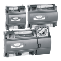
When twin tubing is used from the pickup, split the pickup
tubing a short length to accommodate the connections.
Fig. 11. Airflow pickup connections
Differential Pressure Installation
NOTE: The controller must be powered up for a minimum
of 1 hour before performing the zero calibration for
the air flow sensor.
If controllers are mounted in unusually dusty or
dirty environments, an in-line, 5-micron disposable
air filter (use 5-micron filters compatible with pneu-
matic controls) is recommended for the high-pres-
sure line connected to the air flow pickup.
The tubing from the air flow pickup to the controller
should not exceed three feet (1 m). Any length
greater than this will degrade the flow sensing
accuracy.
Use caution when removing tubing from a connec-
tor. Always pull straight away from the connector or
use diagonal cutters to cut the edge of the tubing
attached to the connector. Never remove by pulling
at an angle.
NOTICE
Dust particle contamination may be present in some
applications. Ensure appropriate measures are taken to
minimize the effect of particulate contamination.
The sense element is in parallel to the air stream and tends
to direct the dust particles in the airflow stream past the
sense element away from the sense bridge. The sense
element is a micro-structure-based device and the bridge
portion of the sense element structure is made up of two
platinum sense elements and a heater. The heater tends to
repel dust particles via a thermophoretic effect past the
heater and tends to keep most dust off the bridge structure.
The heat affect, along with a simple filter, can help to keep
the dust from causing output shifts in the output of the
device. Although the sensor naturally repels dust, some
dust and contamination can still collect on the micro-
structure. Dust adherence to chip edges and channel
surfaces can be prevented by using a simple filter. A
disposable five micron filter used in series on the upstream
side of the airflow divide will provide adequate filtering in
most applications. See Table 4, “Recommended Filter
Suppliers,” on page 11 below for recommended filter
suppliers.
122°F
(50°C)
32°F
(0°C)
± 2.0 HO
(±500 Pa)
Air, N2, O2
non-condensing
Secure with
cable tie
0.20” (5.2 mm)
0.13” (3.5 mm)
0.31 in (8 mm)
Table 4. Recommended Filter Suppliers
Pall Corporation www.pall.com
Acro 50
The filter may be used at a common mode pressure
of 0.17 MPa (24.6 psi) at a temperature of 80 °C [176
°F] May be used with swag lock compression fittings
Approximate pressure drop is 5 kPA at 1 SLPM of
flow.
Acro cap
May be used at an operating temperature of 55 °C
[131 °F] and common mode pressure of 30 psi
Sensors connections are1/4 barb fittings General
Gas filter Pressure drop is 1 psi with a flow of 15
SLPM Fittings are 1/8 barbed tubing.
Parker Balston
www.balstonfilters.com
Model
9933-05
US and EMEA only sales offices. May be used at
common mode pressures up to 125 psi and operating
temperature to 135 °C [275] °F Sensor connections
are 1/4 tube.
MAHLE:
https://catalog.mahleaftermarket.com/eu/product.xhtml?ei
d=184
MAHLE
KL13
Automotive filter

 Loading...