EasyManua.ls Logo

Honeywell CM67NG - User Manual

Honeywell CM67NG
2 pages
Print Icon
To Next Page IconTo Next Page
Loading...
3. SYSTEM CHECK
1. Switch the boiler on
2. Move the
CM67/61NG slider to AUTO or MAN
position(for CM61NG press the AUTO or MAN
button)
3. Adjust the
CM67/61NG setpoint up to the maxi-
mum (30°C) by pressing the TEMP button. The
boiler should come on a few seconds after the
on ame’ symbol appears Check the system opera-
tion changing the setpoint several times, bearing in
mind the switching delay already referred to.
4. FAIL-SAFE MODE SETUP
The failsafe mode selected defi nes the HC60NG output
relay status if the RF communication is lost (e.g. when
room unit stops to communicate due to discharged bat-
teries). The factory setting keeps the relay permanently
off when communications is lost. If the factory setting
needs to be changed follow the instructions below:
1. Move the
CM67NG slider into OFF position (for
CM61NG press the OFF button). Press and hold
the and PROG 3 & 4 buttons together.
2. Press PROG 2 button to enter category 2 param-
eters. Select the parameter 16:LC by pressing
+ or - button.
3. Select the fail-safe mode by pressing TEMP
or
buttons.
0 - when RF communication is lost the relay will be
held in OFF position.
1 - when RF communication is lost the relay output
will cycle at 20% on 80% off.
IMPORTANT:
- To enable the frost protection when RF com-
munication is lost select the fail-safe mode 1.
-
For systems with separate frost protection thermo-
stat or where frost protection is not required select
fail-safe mode 0.
4. Con rm the selected value by pressing the button.
5. Attach appropriate label to the HC60NG relay box
to indicate the selected fail-safe mode.
5. AUTOMATIC OPERATION
HC60NG receives the heat (or cool) demand (0-100%)
signal from
CM61/67NG. The room unit will display
the
symbol whenever more heat is required. Depend-
ing on the demand the HC60NG will switch the heating
(or cooling) device on to match the current require-
ments of the system.
CM67/61NG Programmable Thermostat controls a
single heating system component such as a boiler, a
pump or zone valve. The factory con gured RF link
between the room unit and receiver makes the installa-
tion process fast and easy.
1. START UP
The CM67/61NG room unit is factory bound with
the HC60NG relay box. Therefore no initial binding
between the room unit ( CM67/61NG) and receiver
(HC60NG) is required.
1. Follow the installation diagrams to install and
connect the power supply to HC60NG relay
box. The RF system will commence normal
operation immediately.
NOTE: If the red LED is ashing or if you install a
replacement relay box or room unit, please follow
the procedure described in section 8. BINDING
before system START UP.
2.
To check the RF communication move the
CM67NG slider into OFF position (for CM61NG
press the OFF button) then press the TEMP ,
and PROG 2 buttons for 3 seconds. The unit
will display tESt and it will send test signals to the
receiver switching the green LED on and off every 5
seconds (relay output will remain off) for a maximum
of 10 minutes. When the green LED ashes on/off
every 5 seconds proceed to the next step.
NOTE: If the green LED is not switched at speci ed
intervals follow the procedures described in section
8. BINDING.
2. LOCATING THE CM67/61RF ROOM
UNIT
1. Locate the room unit using the same test mode
as described in 1. START UP. Review the
CM67/
61NG location guidelines (see installation diagram
10
) and nd a suitable location where the signal
transmission is reliable. Reliable transmission is
indicated when the HC60NG relay box is switching
the green LED every 5 seconds. (if the accessory
module is applied the room unit must be located
with the Automatic Time Setting module attached).
2. Install the
CM67/61NG on the wall using the wall
bracket or t it on the optional table stand as shown
in installation diagram
11
.
NOTE: The HC60NG relay will be off.
3. Exit the TEST mode by moving the
CM67NG
slider to the MAN or AUTO position (for CM61NG
press MAN or AUTO button).
A. SINGLE ZONE RF SYSTEM
Honeywell
CM67/61NG Room Unit
& HC60NG Relay Box
INSTALLATION GUIDE
1 2 3
8 9
10
11
Once you have inserted the battery compartment,
after a pause the unit will display information. If this
does not happen or the display shows the
symbol please refer to the trouble shooting section
in the
CM67NG or CM61NG user guides.
HC60NG is a Radio Frequency (RF) device. For the
best performance install in an open space. Leave at
least 30cm distance from any metal objects including
wall boxes and boiler housing.
Do not mount on metal wall boxes.
The
CM67/61NG is a radio frequency device and for the best performance should
be installed in an open space. Leave at least 30cm distance from any metal objects
including wall boxes and at least 1 metre from any other electrical equipment eg.
radio, TV, PC etc. Do not mount on metal wall boxes.
It is recommended that the HC60NG relay box is installed before commencing with
the Room Unit installation.
NG
5
IMPORTANT NOTE 1:
CM60RFNG room unit and HC60NG receiver operate
on 868MHz frequency. They will not communicate with
other RF products using different frequency or com-
munication protocol
NOTE:
HC60NG contains no user serviceable parts. It should
be opened and installed by qualifi ed installer only.
WARNING:
Electrostatic sensitive device! Do not touch the circuit
board.
42010477-003 R1
4
6 7
NOTE: All wiring must be in accordance with IEE regulations
CAUTION: Observe ambient temperature and current limits (see HC60NG wiring label)
> 7mm Ø
< 7mm Ø
ab
a Wall bracket b Table stand (Optional)
max. 2.5mm²
a. Burner (direct control) b. Combi boiler c. Zone valve d. Cooling device
IMPORTANT NOTE 2:
CM67/61NG can be used for two different applications
1. to control a single zone system
or
2. to control a multi-zone system.
If you intend to use it as de ned in point 1 -
read part A. SINGLE ZONE RF SYSTEM rst
If you intend to use it as de ned in point 2 -
read part D. MULTI-ZONE RF SYSTEM rst
Part No:
F42010248-002
The green LED indicates status of the relay output.
Green LED on - relay on
Green LED off - relay off
6. TEMPORARY MANUAL OVERRIDE
Pressing the HC60NG button will override the current
relay position. As soon as next signal is received from
the room unit the HC60NG will return back to automatic
operation as the automatic control has higher priority
than manual operation.
7. COMMUNICATION LOSS
When the RF communication is lost for a period of 1
hour the red LED will be switched on to indicate that
no RF messages have been received during the last
hour.
The HC60NG will also enter the failsafe mode as
selected in Installers Mode (see 4. FAIL-SAFE MODE
SET UP).
To allow manual control of the HC60NG output manual
override is available in fail-safe mode. When RF com-
munication is restored the HC60NG will automatically
return to normal operation.
Move the CM67NG
slider into the OFF
position (for
CM61NG
press the OFF button).
Press and hold the
and PROG 3 & 4 but-
tons together.
Press TEMP or
to change factory
setting.
The display will ash
indicating that a
change has been
made.
Press INFO
button
to con rm the
change is ok.
The display will stop
ashing indicating
that the new value
has been stored.
Adjust other settings using the Installer Set-Up Mode -
Settings Table on the next page.
To exit the Installer Set-Up Mode move the
CM67NG slider
to the AUTO or MAN position (for
CM61NG press the AUTO
or MAN button).
Installer Set-Up Number
(Press
+ or - to change)
e.g. 1 = 12h clock format
Abbreviated Set-Up Description
e.g. CL = Clock format
Factory Setting or New Choice
(Press TEMP
or to change)
e.g. 0 = 24h clock format
e.g. 1 = 12h clock format
Installer Set-Up Mode
Selected
Category 1 Installer Set-Ups
1. PARAMETERS SETTING
Press + or - to go
to the next parame-
ter and follow steps
3 & 4 to make
changes.
1 2
3 4
5
6
7
B. INSTALLER SET-UP MODE
Installer Set-Up Mode allows changing the controller parameters so it can meet speci c application requirements or customers needs. See 4.
INSTALLER SET-UP MODE TABLE for detailed list of con gurable parameters.
8. BINDING
The binding operation described below is required if:
- any of the system components (room unit or relay
box) are replaced
-
HC60NG has incorrect or no binding data stored (e.g.
when pre-bound system pack components have been
mismatched)
During the binding procedure keep approximately 1m
distance between the room unit and the HC60NG.
1. Press and hold the HC60NG push button for 15
sec to reset previously stored data. The red LED
will start to ash at 0.1 s on/0.9 s off. Release the
push button.
2. Press and hold the HC60NG push button for 5 sec
to enter the binding mode. Red LED ashing at 0.5s
on/0.5 s off con rms the binding mode has been
entered.
3. Move the
CM67NG slider to the OFF position (for
CM61NG push the OFF button) and press the
TEMP , and PROG 1 buttons together. The
CM67/61NG will display InSt
4. Press the
button to send the binding signal. The
red LED is switched off to con rm successful bind-
ing operation. If red LED still ashes push the
button again until binding is successful.
5. Follow the START UP and other procedures to
commission the single zone RF system.
Question and Answer IconNeed help?

Do you have a question about the Honeywell CM67NG and is the answer not in the manual?

Summary

A. Single Zone RF System

1. Start Up

Factory bound system, no initial binding needed. Follow diagrams and check RF communication.

2. Locating the CM67;61 RF Room Unit

Find a suitable location for reliable signal transmission and install the unit.

3. System Check

Verify system operation by adjusting the setpoint and checking boiler response.

4. Fail-Safe Mode Setup

Configure the HC60NG relay output status when RF communication is lost.

5. Automatic Operation

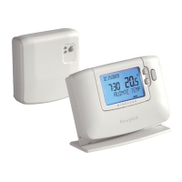
The HC60NG controls the heating device based on demand from the room unit.

B. Installer Set-Up Mode

1. Parameters Setting

Allows changing controller parameters to meet specific application needs or customer requirements.

C. Trouble Shooting Guide

Overview

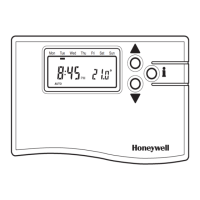
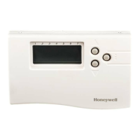
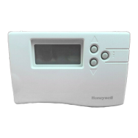
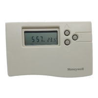
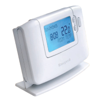
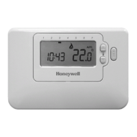
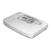
The CM767/61NG is a sophisticated heating control system designed for residential use, offering advanced features for managing room temperature and hot water. It comprises a CM767/61NG Room Unit, which acts as the primary user interface, and a CM67G/60NG Relay Box, responsible for switching the boiler and hot water valve. The system is designed for ease of installation and user-friendly operation, with a focus on energy efficiency and comfort.

Function Description

The core function of the CM767/61NG system is to provide programmable time and temperature control for heating and hot water. The Room Unit allows users to set daily or weekly heating schedules, including different temperature settings for various times of the day. It features a large LCD display that shows current temperature, time, and operating mode, making it easy to monitor and adjust settings. The system supports multiple operating modes, such as Auto, Manual, and Off, providing flexibility to suit different user preferences.

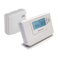
The Room Unit communicates wirelessly with the Relay Box, which is typically installed near the boiler. This wireless communication eliminates the need for extensive wiring between the thermostat and the heating system, simplifying installation. The Relay Box receives commands from the Room Unit and activates or deactivates the boiler and hot water valve accordingly. It also provides visual feedback on its operational status through LED indicators.

A key feature of the CM767/61NG is its support for a Zoning System, allowing for independent temperature control in up to four different heating zones within a home. This is achieved by linking additional CM767/61NG Room Units to the primary system, each controlling a specific zone. This multi-zone capability enhances comfort and energy efficiency by heating only the areas that are in use.

The system also incorporates a "Party" mode, which allows users to temporarily override the programmed schedule for a set duration, maintaining a comfortable temperature during social gatherings. Similarly, a "Holiday" mode enables users to set a reduced temperature for an extended period when the home is unoccupied, saving energy without completely shutting down the heating.

Usage Features

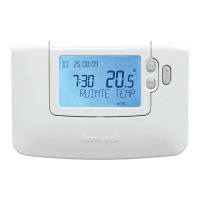
The CM767/61NG Room Unit is designed for intuitive user interaction. The large LCD display provides clear information, and the navigation buttons allow users to easily access and modify settings. The programming interface guides users through the process of setting up heating schedules, making it straightforward to customize the system to individual needs.

For hot water control, the system offers a dedicated button to switch between Auto, On, and Off modes. In Auto mode, hot water is controlled according to a programmed schedule, while On mode provides continuous hot water, and Off mode disables it. This flexibility ensures hot water is available when needed, without unnecessary energy consumption.

The Room Unit features a "Temporary Manual Override" function, allowing users to temporarily adjust the temperature without altering the programmed schedule. This is useful for short-term comfort adjustments. The system also includes a "Fault Safe Mode," which ensures that the heating system continues to operate in a basic manner even if communication between the Room Unit and Relay Box is lost, preventing complete loss of heating.

The multi-zone capability is a significant usage feature, offering enhanced comfort and energy savings. Each zone can be programmed independently, allowing different parts of the house to be heated to different temperatures at different times. This is particularly beneficial in larger homes or homes with varying occupancy patterns.

The "Installer Set-Up Mode" provides advanced configuration options for installers, allowing them to customize various system parameters, such as cycle rates, minimum on-time, and sensor calibration. This ensures the system is optimized for the specific heating system and home environment.

Maintenance Features

The CM767/61NG system is designed for minimal maintenance. The Room Unit is powered by batteries, which are easily replaceable when the low battery indicator appears on the display. The system also features a "Service Interval" function, which can be programmed by the installer to remind users when the heating system is due for maintenance, ensuring optimal performance and longevity.

The Relay Box is a sealed unit with no user-serviceable parts, contributing to its reliability and requiring no routine maintenance. The wireless communication between the Room Unit and Relay Box is robust, but in case of communication issues, the system provides diagnostic information through LED indicators on the Relay Box and error messages on the Room Unit display, aiding in troubleshooting.

The "Fault Safe Mode" acts as a maintenance feature by providing a fallback in case of communication failure, ensuring basic heating functionality is maintained. This prevents a complete system shutdown and allows time for troubleshooting and repair.

The system's design emphasizes durability and long-term performance, with high-quality components and robust construction. Regular cleaning of the Room Unit's exterior with a soft, damp cloth is recommended to maintain its appearance. No internal cleaning or servicing is required by the user. In case of any malfunction or persistent issues, consulting a qualified installer or service technician is recommended.

Honeywell CM67NG Specifications

General IconGeneral
TypeProgrammable Thermostat
Temperature Range5°C to 35°C
DisplayLCD
Contact TypeSPDT (Single Pole Double Throw)
Accuracy±0.5°C
Power Supply2 x AA Batteries
Switching Voltage230V AC
CompatibilityHeating and Cooling Systems

Related product manuals