Error! Use the Home tab to apply Überschrift 1 to the text that you want to appear here. ComfortPoint
TM
Open System
EN1B-0498GE51 R0512
4
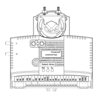
CPO-IO830A Description
Overview
1 2
3
4
5
6 7 8 9 10
11 12
B1 B2
B3
B4
B5 B6
B12
12
6
B11
11
5
B10
10
4
B9
9
3
B8
8
2
B7
7
1
DI
Binary Inputs
G1 G2
41
42
GND
Analog Outputs
AI2
AI3
AI4
14 15 16
AI1
AI5
AI6
AI7
AI8
17
18
19 20
13
Analog Inputs
AO5
AO1
AO6
AO2
AO7
AO3
AO8
AO4
21
25 26
27
28
22
23
24
DO
24V Relays
NO1 NO2 NO3 NO4 NO5 NO6
IN1 IN2
IN3
IN4
IN5
IN6
35
29 30
31 32
33
34
36 37 38 39 40
1 2
3
4
5
6
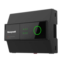
Honeywell
ComfortPoint Open
TM
Install. Instr.
MU1B-0463GE51
!
A1 A2
A3
A4
A5 A6
A7
A8 A9
B1
B2
B3
B4
B5 B6
B7
B8 B9
1
A1
A2
A3
A4
A5
A6
A7
A8
A9
B1
B2
B3
B4
B5
B6
B7
B8
B9
3
A1 A2
A3
A4
A5
A6
A7
A8
A9
B1 B2
B3
B4
B5 B6
B7
B8 B9
2
A1 B1
A2
B2
A3
B3
A4
B4
G1 G2
A5
B5
A6
B6
A7 B7
A8 B8
4
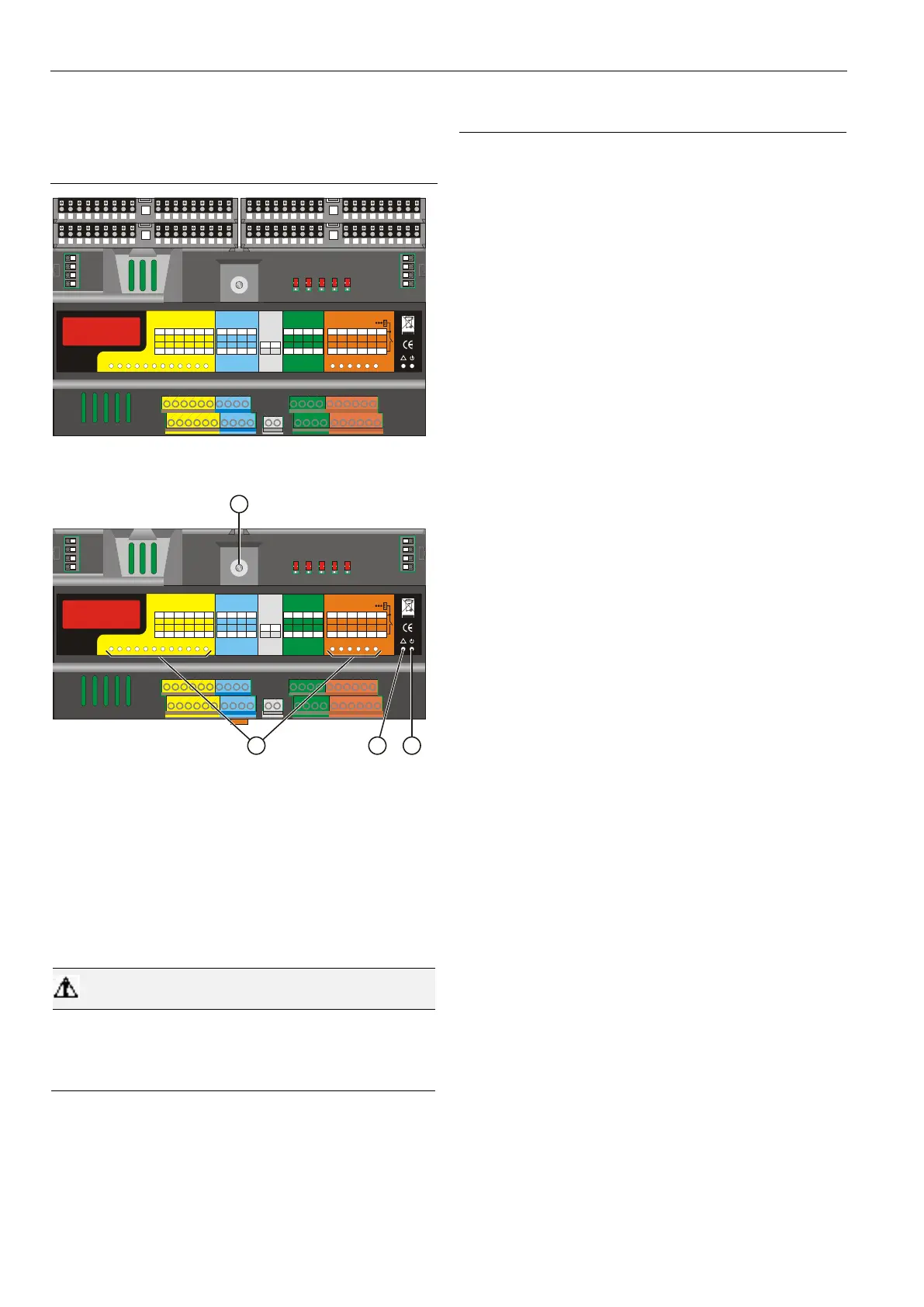
Fig. 2. CPO-IO830A Mixed Panel Bus I/O Module (shown
with aux. terminal packages)
1 2
3
4
5
6 7 8 9 10
11 12
B1 B2
B3
B4
B5 B6
B12
12
6
B11
11
5
B10
10
4
B9
9
3
B8
8
2
B7
7
1
DI
Binary Inputs
G1 G2
41 42
GND
Analog Outputs
AI2
AI3
AI4
14
15 16
AI1
AI5 AI6
AI7
AI8
17
18 19 20
13
Analog Inputs
AO5
AO1
AO6
AO2
AO7
AO3
AO8
AO4
21
25 26
27
28
22
23
24
DO
24V Relays
NO1 NO2 NO3 NO4 NO5 NO6
IN1 IN2
IN3
IN4
IN5 IN6
35
29 30 31 32 33 34
36 37 38 39 40
1 2
3
4
5
6
Honeywell
ComfortPoint Open
TM
Install. Instr.
EN1B-0463GE51
!
1
2
3
4
Fig. 3. CPO-IO830A Mixed Panel Bus I/O Module
Legend
1 Hex switch S2
2 Status LEDs
3 Service LED
4 Power LED
Functionality of service LED and power LED: See section
“Troubleshooting the CPO-IO830A” on page 14.
Risk of electric shock or equipment damage!
It is not permitted to wire the relays of mixed Panel Bus
I/O modules for anything other than low voltage.
Safety Feature
In the event of communication problems, the relay outputs of
the CPO-IO830A Mixed Panel Bus I/O Module will move to
the safety positions you have configured during engineering.

 Loading...