EasyManuals Logo

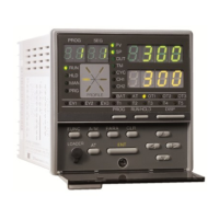
Honeywell DC1010 Wiring Diagram

Honeywell DC1010
4 pages
To Next Page IconTo Next Page
Page #1 background imageLoading...
Page #1 background image
WIRING DIAGRAM
Noise
Filter
POWER
AC 85 ~ 265V
(
50 / 60Hz
)
PV


DC 15 ~ 50V
(option)



4
5
2
3




11
12


13
14



OUTPUT





ALARM





















A
UX. OUT



COMM.
4
5









 

DC1010

Other manuals for Honeywell DC1010

Questions and Answers:

Question and Answer IconNeed help?

Do you have a question about the Honeywell DC1010 and is the answer not in the manual?

Honeywell DC1010 Specifications

General IconGeneral
Control TypeOn/Off, PID
Accuracy±0.25% of span
Operating Temperature0 to 50°C
MountingPanel Mount
Input TypeThermocouple, RTD, mA, V
Output TypeRelay
Supply Voltage100-240 VAC
DisplayLED
Dimensions48 x 48 mm
Number of OutputsUp to 3
Enclosure RatingIP66
AlarmUp to 2 alarms

Related product manuals